-
![[Zener Diode] What is Reverse Current (Leakage Current)?](//electrical-information.com/wp-content/plugins/a3-lazy-load/assets/images/lazy_placeholder.gif)
[Zener Diode] What is Reverse Current (Leakage Current)?
2023/1/24
The reverse current in a zener diode is the current that flows in a minute amount when a reverse voltage is applied. Regarding the reverse current in a zener diode: This article will explain the information below. Reverse Current of Zener Diodes How reverse current is described on the datasheet Reverse Current (Leakage Current) of Zener Diode The above figure shows the "current-voltage characteristic" of a zener diode. In the "current-voltage characteristic," the horizontal axis represents the voltage applied to the zener diode and the vertical axis represents the current flowing through the zener diode. When the reverse voltage (the ...
![[Zener Diode] What is Reverse Current (Leakage Current)?](https://electrical-information.com/wp-content/uploads/2022/07/Zener-Diode-What-it-Reverse-Current-Leakage-Current-150x150.png)
-
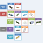
Types of Resistors
2022/11/17
There are many different types of resistors. Regarding the Resistor, this article will explain the information below. Types of ResistorsCharacteristics of each resistance (advantages and disadvantages, etc.) Types of Resistors There are many types of resistors, which can be classified mainly according to their characteristics and materials as shown in the figure above. The resistors that are very inexpensive and most widely used are carbon film resistors. In addition, metal plate resistors with low resistance, high power (several watts), and small inductance are used to detect the current flowing in a circuit. The following is a detailed explanation of each ...
-
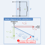
RL Parallel Circuit (Admittance, Phasor Diagram)
2022/11/13
Regarding the RL parallel circuit, this article will explain the information below. Equation, magnitude, vector diagram, and admittance phase angle of RL parallel circuit admittance Admittance of the RL parallel circuit An RL parallel circuit is an electrical circuit consisting of a resistor \(R\) and an inductor \(L\) connected in parallel, driven by a voltage source or current source. The impedance \({\dot{Z}}_R\) of the resistor \(R\) and the impedance \({\dot{Z}}_L\) of the inductor \(L\) can be expressed by the following equations: \begin{eqnarray}{\dot{Z}_R}&=&R\tag{1}\\\\{\dot{Z}_L}&=&jX_L=j{\omega}L\tag{2}\end{eqnarray} , where \({\omega}\) is the angular frequency, which is equal to \(2{\pi}f\), and \(X_L\left(={\omega}L\right)\) is called inductive reactance, ...
-
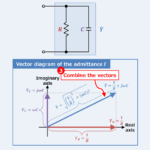
RC Parallel Circuit (Admittance, Phasor Diagram)
2022/11/13
Regarding the RC parallel circuit, this article will explain the information below. Equation, magnitude, vector diagram, and admittance phase angle of RC parallel circuit admittance Admittance of the RC parallel circuit An RC parallel circuit is an electrical circuit consisting of a resistor \(R\) and a capacitor \(C\) connected in parallel, driven by a voltage source or current source. The impedance \({\dot{Z}}_R\) of the resistor \(R\) and the impedance \({\dot{Z}}_C\) of the capacitor \(C\) can be expressed by the following equations: \begin{eqnarray}{\dot{Z}_R}&=&R\tag{1}\\\\{\dot{Z}_C}&=&-jX_C=-j\frac{1}{{\omega}C}=\frac{1}{j{\omega}C}\tag{2}\end{eqnarray} , where \({\omega}\) is the angular frequency, which is equal to \(2{\pi}f\), and \(X_C\left(=\displaystyle\frac{1}{{\omega}C}\right)\) is called capacitive reactance, ...
-
LC Parallel Circuit (Admittance, Phasor Diagram)
2022/11/13
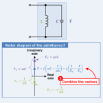
Regarding the LC parallel circuit, this article will explain the information below. Equation, magnitude, vector diagram, and admittance phase angle of LC parallel circuit admittance Admittance of the LC parallel circuit An LC parallel circuit is an electrical circuit consisting of an inductor \(L\) and a capacitor \(C\) connected in parallel, driven by a voltage source or current source. The impedance \({\dot{Z}}_L\) of the inductor \(L\) and the impedance \({\dot{Z}}_C\) of the capacitor \(C\) can be expressed by the following equations: \begin{eqnarray}{\dot{Z}}_L&=&jX_L=j{\omega}L\tag{1}\\\\{\dot{Z}}_C&=&-jX_C=-j\frac{1}{{\omega}C}=\frac{1}{j{\omega}C}\tag{2}\end{eqnarray} , where \({\omega}\) is the angular frequency, which is equal to \(2{\pi}f\), and \(X_L\left(={\omega}L\right)\) is called inductive reactance, ...
-
RLC Parallel Circuit (Admittance, Phasor Diagram)
2022/11/13
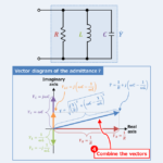
Regarding the RLC parallel circuit, this article will explain the information below. Equation, magnitude, vector diagram, and admittance phase angle of RLC parallel circuit admittance Admittance of the RLC parallel circuit An RLC parallel circuit is an electrical circuit consisting of a resistor \(R\), an inductor \(L\), and a capacitor \(C\) connected in parallel, driven by a voltage source or current source. The impedance \({\dot{Z}}_R\) of the resistor \(R\), the impedance \({\dot{Z}}_L\) of the inductor \(L\), and the impedance \({\dot{Z}}_C\) of the capacitor \(C\) can be expressed by the following equations: \begin{eqnarray}{\dot{Z}_R}&=&R\tag{1}\\\\{\dot{Z}_L}&=&jX_L=j{\omega}L\tag{2}\\\\{\dot{Z}_C}&=&-jX_C=-j\frac{1}{{\omega}C}=\frac{1}{j{\omega}C}\tag{3}\end{eqnarray} , where \({\omega}\) is the angular frequency, which ...
-
Q Factor of RLC Parallel Resonant Circuit
2022/10/20
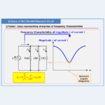
Regarding the Q Factor of RLC Parallel Resonant Circuit, this article will explain the information below. What is the Q factor of RLC parallel resonant circuit?Derivation of Q factor of RLC parallel resonant circuitRelationship between "Q factor" and "current flowing through the inductor L and capacitor C What is the Q factor of RLC parallel resonant circuit? Q factor is a value that expresses the sharpness of the frequency characteristics. A large Q factor makes the frequency characteristics sharper, while a small Q factor makes the frequency characteristics more gradual. The above figure shows the frequency characteristics of the magnitude ...
-
Q Factor of RLC Series Resonant Circuit
2022/10/19
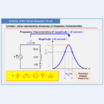
Regarding the Q Factor of RLC Series Resonant Circuit, this article will explain the information below. What is the Q factor of RLC series resonant circuit?Derivation of Q factor of RLC series resonant circuitRelationship between "Q factor" and "voltage across the inductor L and capacitor C What is the Q factor of RLC series resonant circuit? Q factor is a value that expresses the sharpness of the frequency characteristics. A large Q factor makes the frequency characteristics sharper, while a small Q factor makes the frequency characteristics more gradual. The above figure shows the frequency characteristics of the magnitude \(I\) ...
-
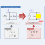
RLC Parallel Resonant Circuit
2022/10/16
Regarding the RLC Parallel Resonant Circuit, this article will explain the information below. What is RLC Parallel Resonant Circuit?"Impedance" and "Resonant Frequency" of RLC Parallel Resonant Circuit"Frequency Characteristics" and "Q factor" of RLC Parallel Resonant Circuit What is RLC Parallel Resonant Circuit? An RLC parallel resonant circuit is a circuit consisting of a resistor \(R\), an inductor \(L\), and a capacitor \(C\) connected in parallel. A circuit in which an inductor \(L\) and a capacitor \(C\) are connected in parallel is called an RLC parallel resonant circuit because it resonates in parallel at some frequency. Some frequency is called resonant ...
-
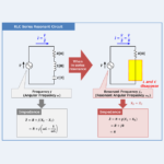
RLC Series Resonant Circuit
2022/10/18
Regarding the RLC Series Resonant Circuit, this article will explain the information below. What is RLC Series Resonant Circuit?"Impedance" and "Resonant Frequency" of RLC Series Resonant Circuit"Frequency Characteristics" and "Q factor" of RLC Series Resonant Circuit What is RLC Series Resonant Circuit? An RLC series resonant circuit is a circuit consisting of a resistor \(R\), an inductor \(L\), and a capacitor \(C\) connected in series. A circuit in which an inductor \(L\) and a capacitor \(C\) are connected in series is called an RLC series resonant circuit because it resonates in series at some frequency. Some frequency is called resonant ...