-

Difference between Induction and Polarization
2022/9/21
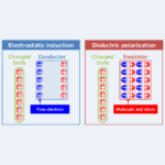
Regarding the Induction and Polarization, this article will explain the information below. Difference between Induction and Polarization[Electrostatic induction and dielectric polarization] Electric field and Electric Potential Induction vs Polarization Electrostatic induction is a phenomenon that occurs when a charged body is brought close to a conductor, causing a bias in the charge inside the conductor. Inside a conductor (a material that conducts electricity, such as a metal) are free electrons. Free electrons are electrons that can move freely inside the conductor and have a negative charge. Therefore, when a charged body is brought close to a conductor, the free electrons ...
-
Difference Between Through-hole, Blind Via, Buried Via, and Land
2022/9/14
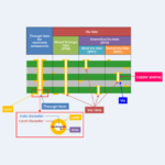
What is the difference between through-hole, blind via, buried via, and land? Regarding the through-hole, blind via, buried via, and land, this article will explain the information below. Difference Between Through-hole, Blind Via, Buried Via, and Land Through-hole First, let us discuss through holes. A through-hole is a hole where the inner surface of a substrate hole is copper plated and electrically connected. There are two types of through holes as follows。 Through-hole for electronic componentsHoles through which terminals of electronic components are inserted for solderingVia holeA hole for the purpose of conduction between layers of a substrate pattern Next, ...
-
Difference Between Transistor (MOSFET) and Relay
2022/9/14
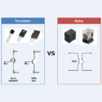
Regarding the Transistor and Relay, this article will explain the information below. Difference Between Transistor and Relay Difference Between Transistor and Relay The figure above shows a transistor and a relay. A transistor (MOSFET) performs switching operations by applying a voltage to its gate terminal (G). On the other hand, a relay performs switching operations by electromagnetic force generated by passing current through a coil. Thus, transistor (MOSFET) and relay can be used as switches. So, what is the difference between a transistor (MOSFET) and a relay? We will now explain the difference between a "transistor (MOSFET)" and a "relay". ...
-
Resistor Color Code Chart (4-Band, 5-Band)
2022/9/7
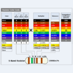
Resistor are marked with a color code indicating "Resistance Value" or "Resistance Tolerance". Regarding the Resistor, this article will explain the information below. Chart of Resistor Color CodeHow to Read Resistor Color Code Chart of Resistor Color Code The color code chart for resistor is shown above. Each color code for resistor has a corresponding number. For example, black is "0", brown is "1", and red is "2". Next, we will explain how to read resistance values using the resistor color code chart. How to Read Resistor Color Code The color code chart of resistors and each resistor (3-band resistor ...
-
Resistor Temperature Rise Calculation
2022/8/31
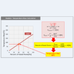
When current flows (voltage is applied) to a resistor, the temperature of the resistor rises. The temperature rise of a resistor depends on the rated power of the resistor. Regarding the Resistor, this article will explain the information below. Resistor Temperature Rise CalculationHeat Dissipated by Resistor Resistor Temperature Rise Calculation When current flows (voltage is applied) to a resistor, the temperature of the resistor rises. The temperature rise of the resistor is indicated by the graph of Temperature rise vs Power dissipation on the data sheet. The vertical axis of the graph is the Percent of Rated Power, and the horizontal ...
-
Resistor Power Derating Curve
2022/8/31
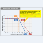
Regarding the Resistor, this article will explain the information below. Resistor Power Derating CurveHow to read the Resistor Power Derating Curve Resistor Power Derating Curve The available power of the resistor depends on the ambient temperature. For this reason, the Resistor Power Derating Curve is included in the resistor datasheet. The vertical axis of the Resistor Power Derating Curve is the percent of rated power, and the horizontal axis is the ambient temperature. By looking at the Resistor Power Derating Curve, you can see how much power is available depending on the ambient temperature (we will explain how to see ...
-
RLC Parallel Circuit (Impedance, Phasor Diagram)
2022/10/28
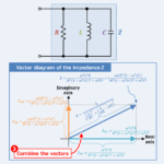
Regarding the RLC parallel circuit, this article will explain the information below. Equation, magnitude, vector diagram, and impedance phase angle of RLC parallel circuit impedance Impedance of the RLC parallel circuit An RLC parallel circuit is an electrical circuit consisting of a resistor \(R\), an inductor \(L\), and a capacitor \(C\) connected in parallel, driven by a voltage source or current source. The impedance \({\dot{Z}}_R\) of the resistor \(R\), the impedance \({\dot{Z}}_L\) of the inductor \(L\), and the impedance \({\dot{Z}}_C\) of the capacitor \(C\) can be expressed by the following equations: \begin{eqnarray}{\dot{Z}_R}&=&R\tag{1}\\\\{\dot{Z}_L}&=&jX_L=j{\omega}L\tag{2}\\\\{\dot{Z}_C}&=&-jX_C=-j\frac{1}{{\omega}C}=\frac{1}{j{\omega}C}\tag{3}\end{eqnarray} , where \({\omega}\) is the angular frequency, which ...
-
LC Parallel Circuit (Impedance, Phasor Diagram)
2022/10/26
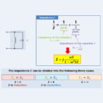
Regarding the LC parallel circuit, this article will explain the information below. Equation, magnitude, vector diagram, and impedance phase angle of LC parallel circuit impedance Impedance of the LC parallel circuit An LC parallel circuit (also known as an LC filter or LC network) is an electrical circuit consisting of an inductor \(L\) and a capacitor \(C\) connected in parallel, driven by a voltage source or current source. The impedance \({\dot{Z}}_L\) of the inductor \(L\) and the impedance \({\dot{Z}}_C\) of the capacitor \(C\) can be expressed by the following equations: \begin{eqnarray}{\dot{Z}}_L&=&jX_L=j{\omega}L\tag{1}\\\\{\dot{Z}}_C&=&-jX_C=-j\frac{1}{{\omega}C}=\frac{1}{j{\omega}C}\tag{2}\end{eqnarray} , where \({\omega}\) is the angular frequency, which is ...
-
Temperature Coefficient of Resistance
2022/8/19
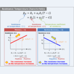
Regarding the Resistor, this article will explain the information below. Resistance Temperature CharacteristicsTemperature Coefficient of Resistance Resistance Temperature Characteristics In general, the resistance of metals increases with increasing temperature, while the resistance of semiconductors decreases with increasing temperature. This change in resistance with temperature can be calculated using the temperature coefficient of resistance \(α_t\), which can be expressed by the following equation: \begin{eqnarray}R_T&=&R_t+α_tR_t(T-t)\\\\&=&R_t\left\{1+α_t(T-t)\right\}\tag{1}\end{eqnarray} , where \(R_T\), \(R_t\), and \(α_t\) indicate the following: \(R_T\):Resistance at temperature \(T{\mathrm{[℃]}}\), units of \({\mathrm{[Ω]}}\).\(R_t\):Resistance at temperature \(t{\mathrm{[℃]}}\), units of \({\mathrm{[Ω]}}\).\(α_t\):Temperature coefficient of resistance. In equation (1), the resistance \(R_t{\mathrm{[Ω]}}\) is obtained when the temperature changes ...
-
Polarity of Resistor
2022/8/18
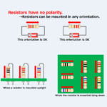
Regarding the Resistor, this article will explain the information below. Polarity of ResistorPolarity of Network Resistor Polarity of Resistor Resistors have no polarity. Therefore, when mounting resistors on a board, it does not matter in which direction they are mounted. There is no need to be aware of positive (+) and negative (-) as with electrolytic capacitors. However, aligning the orientation of the resistors makes the color code easier to read. For example, when the resistor is mounted upright, the color code should be read from top to bottom. When the resistor is mounted lying down, the color code should ...