Regarding the RLC Series Resonant Circuit, this article will explain the information below.
- What is RLC Series Resonant Circuit?
- "Impedance" and "Resonant Frequency" of RLC Series Resonant Circuit
- "Frequency Characteristics" and "Q factor" of RLC Series Resonant Circuit
What is RLC Series Resonant Circuit?
An RLC series resonant circuit is a circuit consisting of a resistor \(R\), an inductor \(L\), and a capacitor \(C\) connected in series.
A circuit in which an inductor \(L\) and a capacitor \(C\) are connected in series is called an RLC series resonant circuit because it resonates in series at some frequency. Some frequency is called resonant frequency. The symbol for the resonant frequency is often expressed as \(f_0\) or \(f_R\) (\(f_0\) is used in this article).
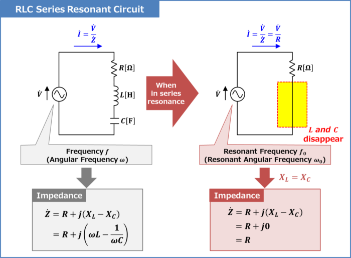
Then, in an RLC series resonant circuit, what is the state when the series resonance is at resonant frequency \(f_0\)?
In conclusion, when the RLC series resonant circuit is in series resonance at the resonant frequency \(f_0\), the reactance \(X_L={\omega}L\) of the inductor \(L\) and the reactance \(X_C=\displaystyle\frac{1}{{\omega}C}\) of the capacitor \(C\) cancel each other out (that is, \(X_L=X_C\)).
At the resonant frequency \(f_0\), the impedance of the RLC series resonant circuit is \({\dot{Z}}=R\) and the current flowing in the RLC series resonant circuit is \({\dot{I}}=\displaystyle\frac{V}{R}\).
Since the expression for the current flowing in the RLC series resonant circuit is \({\dot{I}}=\displaystyle\frac{V}{R}\), the inductor \(L\) and capacitor \(C\) disappear from the expression. In other words, at the resonant frequency \(f_0\), the inductor \(L\) and capacitor \(C\) are apparently eliminated, and only the resistor \(R\) is connected to the circuit.
Next, let us consider the above state from the impedance equation of the RLC series resonant circuit.
Impedance and Resonant Frequency of RLC Series Resonant Circuit
An RLC resonant series circuit is an electrical circuit consisting of a resistor \(R\), an inductor \(L\), and a capacitor \(C\) connected in series.
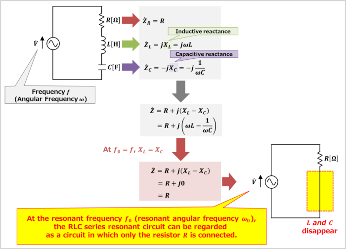
The impedance \({\dot{Z}}_R\) of the resistor \(R\), the impedance \({\dot{Z}}_L\) of the inductor \(L\), and the impedance \({\dot{Z}}_C\) of the capacitor \(C\) can be expressed by the following equations:
\begin{eqnarray}
{\dot{Z}}_R&=&R\tag{1}\\
\\
{\dot{Z}}_L&=&jX_L=j{\omega}L\tag{2}\\
\\
{\dot{Z}}_C&=&-jX_C=-j\frac{1}{{\omega}C}=\frac{1}{j{\omega}C}\tag{3}
\end{eqnarray}
, where \({\omega}\) is the angular frequency, which is equal to \(2{\pi}f\), and \(X_L\) is called inductive reactance, which is the resistive component of inductor \(L\) and \(X_C\) is called capacitive reactance, which is the resistive component of capacitor \(C\).
The impedance \({\dot{Z}}\) of the RLC series circuit is the sum of the respective impedance, and is as follows:
\begin{eqnarray}
{\dot{Z}}&=&{\dot{Z}}_R+{\dot{Z}}_L+{\dot{Z}}_C\\
\\
&=&R+jX_L-jX_C\\
\\
&=&R+j\left(X_L-X_C\right)\\
\\
&=&R+j\left({\omega}L-\frac{1}{{\omega}C}\right)\tag{4}
\end{eqnarray}
The magnitude \(Z\) of the impedance of the RLC series resonant circuit is expressed by the following equation.
\begin{eqnarray}
Z=|{\dot{Z}}|=\sqrt{R^2+\left({\omega}L-\displaystyle\frac{1}{{\omega}C}\right)^2}\tag{5}
\end{eqnarray}
Related article
The following article explains "Impedance of RLC Series Circuits" in detail. If you are interested, please check the link below. 続きを見る
RLC Series Circuit (Impedance, Phasor Diagram)
The RLC series resonant circuit is in series resonance when the reactance \(X_L={\omega}L\) of the inductor \(L\) and the reactance \(X_C=\displaystyle\frac{1}{{\omega}C}\) of the capacitor \(C\) cancel each other (i.e., when \(X_L=X_C\)). If the angular frequency \({\omega}\) at \(X_L=X_C\) is the resonant angular frequency \({\omega}_0\), the following equation holds.
\begin{eqnarray}
X_L&=&X_C\\
\\
{\Leftrightarrow}{{\omega}_0}L&=&\frac{1}{{{\omega}_0}C}\tag{6}\\
\\
{\Leftrightarrow}{{\omega}_0}L-\frac{1}{{{\omega}_0}C}&=&0\tag{7}
\end{eqnarray}
Using equation (6), the resonant angular frequency \({\omega}_0\) and resonant frequency \(f_0\) of the RLC series resonant circuit can be obtained as follows.
\begin{eqnarray}
{{\omega}_0}L&=&\frac{1}{{{\omega}_0}C}\\
\\
{\Leftrightarrow}{{\omega}_0}^2LC&=&1\\
\\
{\Leftrightarrow}{\omega}_0&=&\frac{1}{\sqrt{LC}}\tag{8}\\
\\
{\Leftrightarrow}f_0&=&\frac{1}{2{\pi}\sqrt{LC}}\tag{9}
\end{eqnarray}
From equations (8) and (9), it can be seen that the resonant angular frequency \({\omega}_0\) and resonant frequency \(f_0\) of the RLC series resonant circuit are determined by the inductor \(L\) and capacitor \(C\), and the resistance value \(R\) of the resistor is irrelevant.
Using equation (7), the impedance \({\dot{Z}}\) of the RLC series resonant circuit and its magnitude \(Z\) at the resonant frequency \(f_0\) (resonant angular frequency \({\omega}_0\)) are as follows.
\begin{eqnarray}
{\dot{Z}}&=&R+j\left({\omega}_0L-\frac{1}{{\omega}_0C}\right)=R+j0=R\tag{10}\\
\\
Z&=&\sqrt{R^2+\left({\omega}_0L-\displaystyle\frac{1}{{\omega}_0C}\right)^2}=\sqrt{R^2+0^2}=R\tag{11}
\end{eqnarray}
Let us look at equations (10) and (11). At the resonant frequency \(f_0\) (resonant angular frequency \({\omega}_0\)), the inductor \(L\) and capacitor \(C\) disappear from the impedance equation of the RLC series resonant circuit.
In other words, at the resonant frequency \(f_0\) (resonant angular frequency \({\omega}_0\)), the RLC series resonant circuit can be regarded as a circuit in which the inductor \(L\) and capacitor \(C\) disappear and only the resistor \(R\) is connected.
Q Factor of RLC Series Resonant Circuit
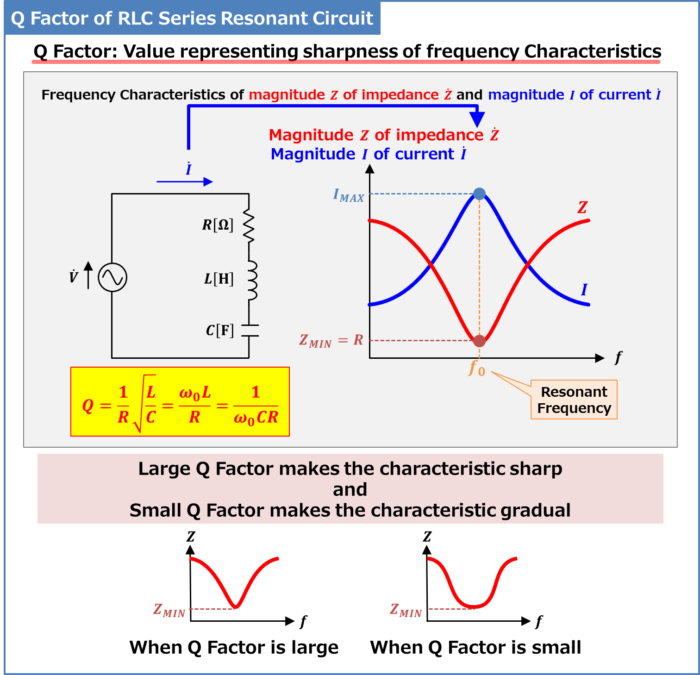
The frequency Characteristics of the magnitude \(Z\) of the impedance of the RLC series resonant circuit expressed in equation (5) is shown in the figure above.
As can be seen from the frequency characteristics, the magnitude \(Z\) of the impedance of the RLC series resonant circuit has a minimum value \(Z_{MIN}=R\) at the resonant frequency \(f_0\) and increases as the resonant frequency moves away from \(f_0\).
Therefore, the magnitude \(I\) of the current flowing in the RLC series resonant circuit at the resonant frequency \(f_0\) is the maximum value \(I_{MAX}\), and \(I_{MAX}\) is expressed by the following equation.
\begin{eqnarray}
I_{MAX}&=&\frac{V}{Z_{MIN}}\\
\\
&=&\frac{V}{R}\tag{12}
\end{eqnarray}
Resonant circuits also have a value called the Q factor. The larger the Q factor, the sharper the frequency response, and the smaller the Q factor, the more gradual the response.
In the case of an RLC series resonant circuit, the Q factor is expressed by the following equation.
\begin{eqnarray}
Q=\frac{1}{R}\sqrt{\frac{L}{C}}=\frac{{\omega}_0L}{R}=\frac{1}{{\omega}_0CR}\tag{13}
\end{eqnarray}
The smaller the resistance of the resistor \(R\), the larger the inductance of the inductor \(L\), and the smaller the capacitance of the capacitor \(C\), the larger the Q factor, resulting in a sharper frequency response.
Related article
The following article explains the "Q factor RLC Series Resonant Circuit" in detail. If you are interested, please check it out from the link below. 続きを見る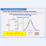
Q Factor of RLC Series Resonant Circuit
Summary
This article described the following information about "RLC Series Resonant Circuit".
- What is RLC Series Resonant Circuit?
- "Impedance" and "Resonant Frequency" of RLC Series Resonant Circuit
- "Frequency Characteristics" and "Q factor" of RLC Series Resonant Circuit
Thank you for reading.