-

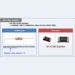
What is a Zero-Ohm Resistor?
2022/10/13
When looking at a printed circuit board, a zero-ohm resistor with a resistance value of 0Ω may be mounted. Have you ever wondered the following questions about zero-ohm resistors? Why connect a zero-ohm resistor? What is its use?Why not use a jumper wire instead of a zero-ohm resistor?What is the difference between a zero-ohm resistor and a jumper wire? This article summarizes various aspects of zero-ohm resistors to solve these questions. I will now begin to explain. What is a Zero-Ohm Resistor? A zero-ohm resistor is, as the name implies, a resistor with a resistance value of zero ohms (0Ω). ...
-
RL Series Circuit (Power Factor, Active and Reactive Power)
2022/10/7
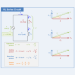
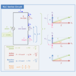
Regarding the RL series circuit, this article will explain the information below. Power factor \({\cos}{\theta}\) of the RL series CircuitActive power \(P\), Reactive power \(Q\), and Apparent power \(S\) of the RL series circuit [RL Circuit] Power factor & Active, Reactive, and Apparent power Shown in the figure above is an RL series circuit with resistor \(R\), inductor \(L\), and capacitor \(C\) connected in series. As an example, the parameters of the RL series circuit are as follows. Supply voltage: \({\dot{V}}=200{\;}{\mathrm{[V]}}\)Frequency of power supply voltage: \(f=60{\;}{\mathrm{[Hz]}}\)Resistance value of resistor: \(R=50\sqrt{3}{\;}{\mathrm{[{\Omega}]}}\)Inductance of inductor: \(L=132.7{\;}{\mathrm{[mH]}}\) The power factor \({\cos}{\theta}\), active power \(P\), ...
-
RC Series Circuit (Power Factor, Active and Reactive Power)
2022/10/7
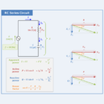
Regarding the RC series circuit, this article will explain the information below. Power factor \({\cos}{\theta}\) of the RC series CircuitActive power \(P\), Reactive power \(Q\), and Apparent power \(S\) of the RC series circuit [RC Circuit] Power factor & Active, Reactive, and Apparent power Shown in the figure above is an RC series circuit with resistor \(R\) and capacitor \(C\) connected in series. As an example, the parameters of the RC series circuit are as follows. Supply voltage: \({\dot{V}}=200{\;}{\mathrm{[V]}}\)Frequency of power supply voltage: \(f=60{\;}{\mathrm{[Hz]}}\)Resistance value of resistor: \(R=50\sqrt{3}{\;}{\mathrm{[{\Omega}]}}\)Capacitance of capacitor: \(C=53{\;}{\mathrm{[μF]}}\) The power factor \({\cos}{\theta}\), active power \(P\), reactive power ...
-
RLC Series Circuit (Power Factor, Active and Reactive Power)
2022/10/7
Regarding the RLC series circuit, this article will explain the information below. Power factor \({\cos}{\theta}\) of the RLC series CircuitActive power \(P\), Reactive power \(Q\), and Apparent power \(S\) of the RLC series circuit [RLC Circuit] Power factor & Active, Reactive, and Apparent power Shown in the figure above is an RLC series circuit with resistor \(R\), inductor \(L\), and capacitor \(C\) connected in series. As an example, the parameters of the RLC series circuit are as follows. Supply voltage: \({\dot{V}}=200{\;}{\mathrm{[V]}}\)Frequency of power supply voltage: \(f=60{\;}{\mathrm{[Hz]}}\)Resistance value of resistor: \(R=50\sqrt{3}{\;}{\mathrm{[{\Omega}]}}\)Inductance of inductor: \(L=265.4{\;}{\mathrm{[mH]}}\)Capacitance of capacitor: \(C=53{\;}{\mathrm{[μF]}}\) The power factor \({\cos}{\theta}\), ...
-
RC Parallel Circuit (Power Factor, Active and Reactive Power)
2022/10/7
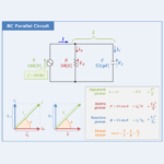
Regarding the RC parallel circuit, this article will explain the information below. Power factor \({\cos}{\theta}\) of the RC parallel CircuitActive power \(P\), Reactive power \(Q\), and Apparent power \(S\) of the RC parallel circuit [RC Circuit] Power factor & Active, Reactive, and Apparent power Shown in the figure above is an RC parallel circuit with resistor \(R\) and capacitor \(C\) connected in parallel. As an example, the parameters of the RC parallel circuit are as follows. Supply voltage: \({\dot{V}}=100{\;}{\mathrm{[V]}}\)Frequency of power supply voltage: \(f=60{\;}{\mathrm{[Hz]}}\)Resistance value of resistor: \(R=50{\;}{\mathrm{[{\Omega}]}}\)Capacitance of capacitor: \(C=53{\;}{\mathrm{[μF]}}\) The power factor \({\cos}{\theta}\), active power \(P\), reactive power ...
-
RL Parallel Circuit (Power Factor, Active and Reactive Power)
2022/10/7
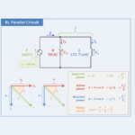
Regarding the RL parallel circuit, this article will explain the information below. Power factor \({\cos}{\theta}\) of the RL parallel CircuitActive power \(P\), Reactive power \(Q\), and Apparent power \(S\) of the RL parallel circuit [RL Circuit] Power factor & Active, Reactive, and Apparent power Shown in the figure above is an RL parallel circuit with resistor \(R\) and inductor \(L\) connected in parallel. As an example, the parameters of the RL parallel circuit are as follows. Supply voltage: \({\dot{V}}=100{\;}{\mathrm{[V]}}\)Frequency of power supply voltage: \(f=60{\;}{\mathrm{[Hz]}}\)Resistance value of resistor: \(R=50{\;}{\mathrm{[{\Omega}]}}\)Inductance of inductor: \(L=132.7{\;}{\mathrm{[mH]}}\) The power factor \({\cos}{\theta}\), active power \(P\), reactive power ...
-
RLC Parallel Circuit (Power Factor, Active and Reactive Power)
2022/10/7
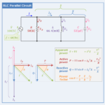
Regarding the RLC parallel circuit, this article will explain the information below. Power factor \({\cos}{\theta}\) of the RLC parallel CircuitActive power \(P\), Reactive power \(Q\), and Apparent power \(S\) of the RLC parallel circuit [RLC Circuit] Power factor & Active, Reactive, and Apparent power Shown in the figure above is an RLC parallel circuit with resistor \(R\), inductor \(L\), and capacitor \(C\) connected in parallel. As an example, the parameters of the RLC parallel circuit are as follows. Supply voltage: \({\dot{V}}=100{\;}{\mathrm{[V]}}\)Frequency of power supply voltage: \(f=60{\;}{\mathrm{[Hz]}}\)Resistance value of resistor: \(R=50{\;}{\mathrm{[{\Omega}]}}\)Inductance of inductor: \(L=66.4{\;}{\mathrm{[mH]}}\)Capacitance of capacitor: \(C=53{\;}{\mathrm{[μF]}}\) The power factor \({\cos}{\theta}\), ...
-
Difference between VCC, VEE, VDD, and VSS
2022/9/30
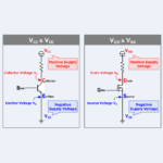
Looking at the schematic, VCC, VEE, VDD, and VSS are used for supply voltage. What is VCC, VEE, VDD, and VSS?What does the "CC" in "VCC" stand for?What does the "EE" in "VEE" stand for?What does the "DD" in "VDD" stand for?What does the "SS" in "VSS" stand for? This article explains the meaning and differences between VCC, VEE, VDD, and VSS. Meaning and Difference of VCC, VEE, VDD, and VSS The meanings and differences of VCC, VEE, VDD, and VSS used in the supply voltage are shown below. VCCVCC is used as the positive supply voltage for circuits using ...
-
Electrostatic Induction (Explanation, Principle)
2022/9/21
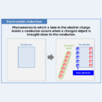
Regarding the Electrostatic Induction, this article will explain the information below. Explanation of Electrostatic InductionPrinciple of Electrostatic Induction Electrostatic Induction Electrostatic induction is a phenomenon that occurs when a charged body is brought close to a conductor, causing a bias in the charge inside the conductor. Inside a conductor (a material that conducts electricity, such as a metal) are free electrons. Free electrons are electrons that can move freely inside the conductor and have a negative charge. Therefore, when a charged body is brought close to a conductor, the free electrons inside the conductor are subjected to electrostatic force and ...
-
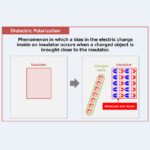
Dielectric Polarization (Explanation, Principle)
2022/9/21
Regarding the Dielectric Polarization, this article will explain the information below. Explanation of Dielectric PolarizationPrinciple of Dielectric Polarization Dielectric Polarization Dielectric polarization is a phenomenon that occurs when a charged body is brought close to an insulator, causing a bias in the charge inside the insulator. When a charged body is placed close to an insulator (a material that does not conduct electricity, such as an underlay), the electrons (which have a negative charge) in the molecules and atoms inside the insulator are subjected to electrostatic forces. The electrons inside the insulator are not free electrons that can move freely. ...