-

RC Parallel Circuit (Impedance, Phasor Diagram)
2022/10/26
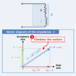
Regarding the RC parallel circuit, this article will explain the information below. Equation, magnitude, vector diagram, and impedance phase angle of RC parallel circuit impedance Iimpedance of the RC parallel circuit An RC parallel circuit (also known as an RC filter or RC network) is an electrical circuit consisting of a resistor \(R\) and a capacitor \(C\) connected in parallel, driven by a voltage source or current source. The impedance \({\dot{Z}}_R\) of the resistor \(R\) and the impedance \({\dot{Z}}_C\) of capacitor \(C\) can be expressed by the following equations: \begin{eqnarray}{\dot{Z}_R}&=&R\tag{1}\\\\{\dot{Z}_C}&=&-jX_C=-j\frac{1}{{\omega}C}=\frac{1}{j{\omega}C}\tag{2}\end{eqnarray} ,where \({\omega}\) is the angular frequency, which is equal to ...
-
RL Parallel Circuit (Impedance, Phasor Diagram)
2022/10/26
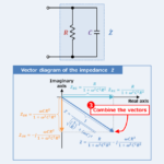
Regarding the RL parallel circuit, this article will explain the information below. Equation, magnitude, vector diagram, and impedance phase angle of RL parallel circuit impedance Impedance of the RL parallel circuit An RL parallel circuit (also known as an RL filter or RL network) is an electrical circuit consisting of a resistor \(R\) and an inductor \(L\) connected in parallel, driven by a voltage source or current source. The impedance \({\dot{Z}}_R\) of the resistor \(R\) and the impedance \({\dot{Z}}_L\) of the inductor \(L\) can be expressed by the following equations: \begin{eqnarray}{\dot{Z}}_R&=&R\tag{1}\\\\{\dot{Z}}_L&=&jX_L=j{\omega}L\tag{2}\end{eqnarray} ,where \({\omega}\) is the angular frequency, which is equal ...
-
Rated Voltage and Maximum Working Voltage of Resistor
2022/8/10
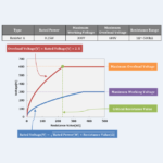
Regarding the Resistor, this article will explain the information below. Rated VoltageMaximum Working Voltage Rated Voltage and Maximum Working Voltage The data sheet of a resistor lists the rated power, maximum working voltage, and resistance range as shown in the figure above. The rated voltage of a resistor is the maximum value of DC or AC voltage (RMS value) that can be continuously applied to the resistor. The rated voltage can be calculated using the rated power and the resistance value, and is expressed by the following equation: \begin{eqnarray}\mbox{Rated Voltage}{\mathrm{[V]}}=\sqrt{\mbox{Rated Power}{\mathrm{[W]}}×\mbox{Resistance Value}{\mathrm{[{\Omega}]}}}\end{eqnarray} From the above equation, the larger the resistance ...

-
Overload Voltage and Maximum Overload Voltage of Resistor
2022/10/7
Regarding the Resistor, this article will explain the information below. Overload Voltage of ResistorMaximum Overload Voltage of Resistor Overload Voltage and Maximum Overload Voltage The overload voltage of the resistor is the maximum value of voltage that can be applied to the resistor for a short time in the overload test. Generally, the overload voltage of the resistor is 2.5 times the rated voltage. However, the voltage should not exceed the maximum overload voltage. The maximum overload voltage of the resistor is given in the data sheet. The relationship between overload voltage and rated voltage is expressed by the following ...
-
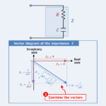
RLC Series Circuit (Impedance, Phasor Diagram)
2022/10/28
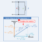
Regarding the RLC series circuit, this article will explain the information below. Equation, magnitude, vector diagram, and impedance phase angle of RLC series circuit impedance Impedance of the RLC series circuit An RLC series circuit (also known as an RLC filter or RLC network) is an electrical circuit consisting of a resistor \(R\), an inductor \(L\), and a capacitor \(C\) connected in series, driven by a voltage source or current source. The impedance \({\dot{Z}}_R\) of the resistor \(R\), the impedance \({\dot{Z}}_L\) of the inductor \(L\), and the impedance \({\dot{Z}}_C\) of the capacitor \(C\) can be expressed by the following equations: ...
-
LC Series Circuit (Impedance, Phasor Diagram)
2022/10/28
Regarding the LC series circuit, this article will explain the information below. Equation, magnitude, vector diagram, and impedance phase angle of LC series circuit impedance Impedance of the LC series circuit An LC series circuit (also known as an LC filter or LC network) is an electrical circuit consisting of an inductor \(L\) and a capacitor \(C\) connected in series, driven by a voltage source or current source. The impedance \({\dot{Z}}_L\) of the inductor \(L\) and the impedance \({\dot{Z}}_C\) of the capacitor \(C\) can be expressed by the following equations: \begin{eqnarray}{\dot{Z}}_L&=&jX_L=j{\omega}L\\\\{\dot{Z}}_C&=&-jX_C=-j\frac{1}{{\omega}C}=\frac{1}{j{\omega}C}\end{eqnarray} ,where \({\omega}\) is the angular frequency, which is equal ...
-
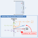
RC Series Circuit (Impedance, Phasor Diagram)
2022/10/28
Regarding the RC series circuit, this article will explain the information below. Equation, magnitude, vector diagram, and impedance phase angle of RC series circuit impedance Impedance of the RC series circuit An RC series circuit (also known as an RC filter or RC network) is an electrical circuit consisting of a resistor \(R\) and a capacitor \(C\) connected in series, driven by a voltage source or current source. The impedance \({\dot{Z}}_R\) of the resistor \(R\) and the impedance \({\dot{Z}}_C\) of the capacitor \(C\) can be expressed by the following equations: \begin{eqnarray}{\dot{Z}}_R&=&R\\\\{\dot{Z}}_C&=&-jX_C=-j\frac{1}{{\omega}C}=\frac{1}{j{\omega}C}\end{eqnarray} ,where \({\omega}\) is the angular frequency, which is equal ...
-
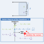
RL Series Circuit (Impedance, Phasor Diagram)
2022/10/28
Regarding the RL series circuit, this article will explain the information below. Equation, magnitude, vector diagram, and impedance phase angle of RL series circuit impedance Impedance of the RL series circuit An RL series circuit (also known as an RL filter or RL network) is an electrical circuit consisting of a resistor \(R\) and an inductor \(L\) connected in series, driven by a voltage source or current source. The impedance \({\dot{Z}}_R\) of the resistor \(R\) and the impedance \({\dot{Z}}_L\) of the inductor \(L\) can be expressed by the following equations: \begin{eqnarray}{\dot{Z}}_R&=&R\\\\{\dot{Z}}_L&=&jX_L=j{\omega}L\end{eqnarray} ,where \({\omega}\) is the angular frequency, which is equal ...