Regarding the Q Factor of RLC Series Resonant Circuit, this article will explain the information below.
- What is the Q factor of RLC series resonant circuit?
- Derivation of Q factor of RLC series resonant circuit
- Relationship between "Q factor" and "voltage across the inductor L and capacitor C
What is the Q factor of RLC series resonant circuit?
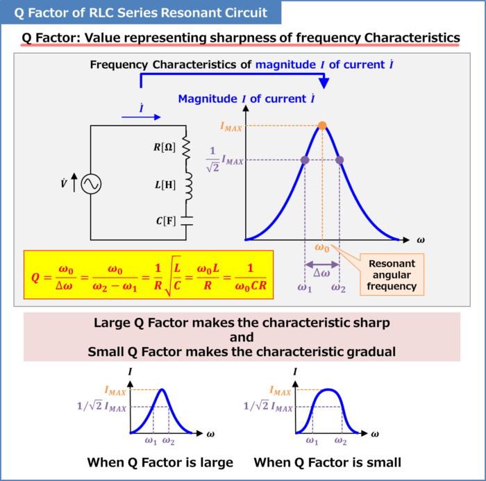
Q factor is a value that expresses the sharpness of the frequency characteristics. A large Q factor makes the frequency characteristics sharper, while a small Q factor makes the frequency characteristics more gradual.
The above figure shows the frequency characteristics of the magnitude \(I\) of the current flowing in an RLC series resonant circuit. The RLC series resonant circuit is a circuit consisting of a resistor \(R\), an inductor \(L\), and a capacitor \(C\) connected in series, and the magnitude \(I\) of current reaches its maximum value \(I_{MAX}\) at the angular frequency \({\omega}_0\left(=\displaystyle\frac{1}{\sqrt{LC}}\right)\) where the inductor \(L\) and capacitor \(C\) resonate.
In an RLC series resonant circuit, the Q factor is expressed by the following equation (the derivation of the following equation will be explained later).
Q factor of RLC series resonant circuit
\begin{eqnarray}
Q=\frac{{\omega}_0}{{\Delta}{\omega}}=\frac{{\omega}_0}{{\omega}_2-{\omega}_1}=\frac{1}{R}\sqrt{\frac{L}{C}}=\frac{{\omega}_0L}{R}=\frac{1}{{\omega}_0CR}\tag{1}
\end{eqnarray}
In the above equation, \({\omega}_0\) is the resonant angular frequency, \({\omega}_1\) and \({\omega}_2\) are the angular frequencies when the magnitude \(I\) of the current flowing in the RLC series resonant circuit is \(\displaystyle\frac{1}{\sqrt{2}}\) times the magnitude of \(I_{MAX}\) (\({\omega}_1{<}{\omega}_2\)), \(R\) is the resistance of the resistor, \(L\) is the inductance of the inductor, and \(C\) is the capacitance of the capacitor.
From equation (1), the smaller \({\Delta}{\omega}(={\omega}_2-{\omega}_1)\) (the sharper the frequency response), the larger the Q factor.
Supplement
The Q factor is a measure of the low loss of a resonant circuit. In the case of an RLC series resonant circuit, the smaller the resistance \(R\), the larger the Q factor. This is because the smaller the resistance \(R\), the smaller the loss generated by the resistor.
Related article
The following article explains the "RLC Series Resonant Circuit" in detail. If you are interested, please check it out from the link below. 続きを見る
RLC Series Resonant Circuit
Derivation of Q factor of RLC series resonant circuit
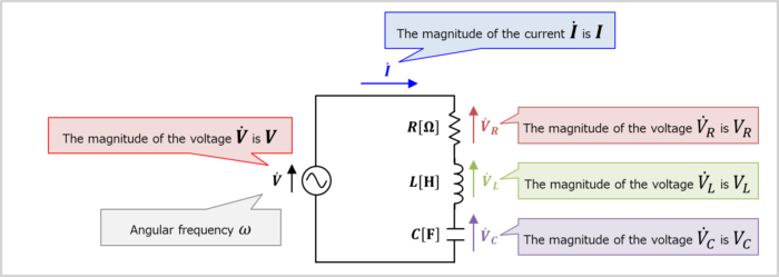
The RLC resonant series circuit is an electrical circuit consisting of a resistor \(R\), an inductor \(L\), and a capacitor \(C\) connected in series.
When the resistance of resistor \(R\) is \(R{\mathrm{[{\Omega}]}}\), the inductance of inductor \(L\) is \(L{\mathrm{[H]}}\), and the capacitance of capacitor \(C\) is \(C{\mathrm{[F]}}\), the impedance \({\dot{Z}}\) of the RLC series resonant circuit becomes the following equation.
\begin{eqnarray}
{\dot{Z}}=R+j\left({\omega}L-\frac{1}{{\omega}C}\right)\tag{2}
\end{eqnarray}
, where \({\omega}\) is the angular frequency, which is equal to \(2{\pi}f\).
The magnitude \(Z\) of the impedance of the RLC series resonant circuit is expressed by the following equation.
\begin{eqnarray}
Z=|{\dot{Z}}|=\sqrt{R^2+\left({\omega}L-\displaystyle\frac{1}{{\omega}C}\right)^2}\tag{3}
\end{eqnarray}
Related article
The following article explains "Impedance of RLC Series Circuits" in detail. If you are interested, please check the link below. 続きを見る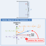
RLC Series Circuit (Impedance, Phasor Diagram)
Therefore, when the magnitude of the supply voltage is \(V\), the magnitude \(I\) of the current flowing in the RLC series resonant circuit is expressed by the following equation.
\begin{eqnarray}
I=\frac{V}{Z}=\frac{V}{\sqrt{R^2+\left({\omega}L-\displaystyle\frac{1}{{\omega}C}\right)^2}}\tag{4}
\end{eqnarray}
At the angular frequency (resonant angular frequency) )\({\omega}_0\left(=\displaystyle\frac{1}{\sqrt{LC}}\right)\), the inductor \(L\) and the capacitor \(C\) are in resonance, and the following equation holds.
\begin{eqnarray}
{\omega}_0&=&\frac{1}{\sqrt{LC}}\\
\\
{\Leftrightarrow}{{\omega}_0}^2&=&\frac{1}{LC}\\
\\
{\Leftrightarrow}{{\omega}_0}L&=&\frac{1}{{{\omega}_0}C}\\
\\
{\Leftrightarrow}{{\omega}_0}L-\frac{1}{{{\omega}_0}C}&=&0\tag{5}
\end{eqnarray}
The reactance \(X_L\) of the inductor \(L\) is \(X_L={\omega}L\). On the other hand, the reactance \(X_C\) of the capacitor \(C\) is \(X_C=\displaystyle\frac{1}{{\omega}C}\). As can be seen from equation (5), "reactance \(X_L\) of inductor \(L\)" and "reactance \(X_C\) of capacitor \(C\)" are equal at the resonant angular frequency \({\omega}_0\).
At resonant angular frequency \({\omega}_0\), the magnitude \(I\) of the current flowing in the RLC series circuit is the maximum value \(I_{MAX}\). \(I_{MAX}\) is expressed by the following equation.
\begin{eqnarray}
I_{MAX}&=&\frac{V}{\sqrt{R^2+\left({\omega}_0L-\displaystyle\frac{1}{{\omega}_0C}\right)^2}}\\
\\
&=&\frac{V}{\sqrt{R^2+0^2}}\\
\\
&=&\frac{V}{R}\tag{6}
\end{eqnarray}
From equations (4) and (6), we obtain the following equation.
\begin{eqnarray}
\frac{I}{I_{MAX}}&=&\frac{\displaystyle\frac{V}{\sqrt{R^2+\left({\omega}L-\displaystyle\frac{1}{{\omega}C}\right)^2}}}{\displaystyle\frac{V}{R}}\\
\\
&=&\frac{R}{\sqrt{R^2+\left({\omega}L-\displaystyle\frac{1}{{\omega}C}\right)^2}}\\
\\
&=&\frac{1}{\sqrt{1+\left(\displaystyle\frac{{\omega}L}{R}-\displaystyle\frac{1}{{\omega}CR}\right)^2}}\tag{7}
\end{eqnarray}
Here, when "the magnitude \(I\) of the current flowing in the RLC series resonance circuit" is \(\displaystyle\frac{1}{\sqrt{2}}\) times "the magnitude \(I_{MAX}\) of the current flowing at resonance" (when \(I=\displaystyle\frac{1}{\sqrt{2}}I_{MAX}\)), the following equation is obtained.
\begin{eqnarray}
\frac{\displaystyle\frac{1}{\sqrt{2}}I_{MAX}}{I_{MAX}}&=&\frac{1}{\sqrt{1+\left(\displaystyle\frac{{\omega}L}{R}-\displaystyle\frac{1}{{\omega}CR}\right)^2}}\\
\\
{\Leftrightarrow}\frac{1}{\sqrt{2}}&=&\frac{1}{\sqrt{1+\left(\displaystyle\frac{{\omega}L}{R}-\displaystyle\frac{1}{{\omega}CR}\right)^2}}\\
\\
{\Leftrightarrow}\frac{{\omega}L}{R}-\frac{1}{{\omega}CR}&=&±1\tag{8}
\end{eqnarray}
By using equation (8), the angular frequency \({\omega}\) can be obtained for the "Case \(\displaystyle\frac{{\omega}L}{R}-\displaystyle\frac{1}{{\omega}CR}=1\)" and the "Case \(\displaystyle\frac{{\omega}L}{R}-\displaystyle\frac{1}{{\omega}CR}=-1\)".
Case \(\displaystyle\frac{{\omega}L}{R}-\displaystyle\frac{1}{{\omega}CR}=1\)
Transforming "\(\displaystyle\frac{{\omega}L}{R}-\displaystyle\frac{1}{{\omega}CR}=1\)", we obtain the following equation.
\begin{eqnarray}
\displaystyle\frac{{\omega}L}{R}-\displaystyle\frac{1}{{\omega}CR}=1\\
\\
{\Leftrightarrow}LC{\omega}^2-RC{\omega}-1=0\tag{9}
\end{eqnarray}
Solving equation (9), the angular frequency \({\omega}\) is expressed by the following equation.
\begin{eqnarray}
{\omega}=\frac{RC+\sqrt{(RC)^2+4LC}}{2LC}\tag{10}
\end{eqnarray}
In the above equation, the root (√) is preceded by "+ (plus)" because \({\omega}{>}0\) is considered. Let \({\omega}\) in equation (10) be \({\omega}_2\).
Case \(\displaystyle\frac{{\omega}L}{R}-\displaystyle\frac{1}{{\omega}CR}=-1\)
Transforming "\(\displaystyle\frac{{\omega}L}{R}-\displaystyle\frac{1}{{\omega}CR}=-1\)", we obtain the following equation.
\begin{eqnarray}
\displaystyle\frac{{\omega}L}{R}-\displaystyle\frac{1}{{\omega}CR}=-1\\
\\
{\Leftrightarrow}LC{\omega}^2+RC{\omega}-1=0\tag{11}
\end{eqnarray}
Solving equation (11), the angular frequency \({\omega}\) is expressed by the following equation.
\begin{eqnarray}
{\omega}=\frac{-RC+\sqrt{(RC)^2+4LC}}{2LC}\tag{12}
\end{eqnarray}
In the above equation, the root (√) is preceded by "+ (plus)" because \({\omega}{>}0\) is considered. Let \({\omega}\) in equation (12) be \({\omega}_1\).
Therefore, \({\Delta}{\omega}(={\omega}_2-{\omega}_1)\) is expressed by the following equation.
\begin{eqnarray}
{\Delta}{\omega}&=&{\omega}_2-{\omega}_1\\
\\
&=&\frac{RC+\sqrt{(RC)^2+4LC}}{2LC}-\frac{-RC+\sqrt{(RC)^2+4LC}}{2LC}\\
\\
&=&\frac{R}{L}\tag{13}
\end{eqnarray}
Note that \({\Delta}{\omega}\) is called Bandwidth. From the above, the Q factor of the RLC series resonant circuit is expressed by the following equation.
\begin{eqnarray}
Q=\frac{{\omega}_0}{{\Delta}{\omega}}=\frac{{\omega}_0}{{\omega}_2-{\omega}_1}&=&\frac{\displaystyle\frac{1}{\sqrt{LC}}}{\displaystyle\frac{R}{L}}\\
\\
&=&\frac{1}{R}\sqrt{\frac{L}{C}}\tag{14}
\end{eqnarray}
In addition, using "\({\omega}_0=\displaystyle\frac{1}{\sqrt{LC}}\)" in equation (14), the following equation is obtained.
\begin{eqnarray}
Q=\frac{1}{R}\sqrt{\frac{L}{C}}=\frac{{\omega}_0L}{R}=\frac{1}{{\omega}_0CR}\tag{15}
\end{eqnarray}
This concludes the derivation of the Q factor of the RLC series resonant circuit; let's look at the Q factor in a little more detail.
Since the current flowing in the RLC series resonant circuit at the resonant angular frequency \({\omega}_0\) is \(I_{MAX}\), the "magnitude \(V_R\) of the voltage across the resistor \(R\)", the "magnitude \(V_L\) of the voltage across the inductor \(L\)", and the "magnitude \(V_C\) of the voltage across the capacitor \(C\)" are as follows.
\begin{eqnarray}
V_R&=&R×I_{MAX}\tag{16}\\
\\
V_L&=&{\omega}_0L×I_{MAX}\tag{17}\\
\\
V_C&=&\frac{1}{{\omega}_0C}×I_{MAX}\tag{18}
\end{eqnarray}
From equations (16) to (18), the Q factor can be transformed as follows.
\begin{eqnarray}
Q&=&\frac{{\omega}_0L}{R}=\frac{{\omega}_0L×I_{MAX}}{R×I_{MAX}}=\frac{V_L}{V_R}\tag{19}\\
\\
Q&=&\frac{1}{{\omega}_0CR}=\frac{{\omega}_0L×I_{MAX}}{R×I_{MAX}}=\frac{V_C}{V_R}\tag{20}
\end{eqnarray}
Therefore, the Q factor can be said to be the ratio of "the magnitude \(V_R\) of the voltage across the resistor \(R\)" to "the magnitude \(V_L\) of the voltage across the inductor \(L\)" or "the magnitude \(V_C\) of the voltage across the capacitor \(C\)"
Relationship between "Q factor" and "voltage across the inductor L and capacitor C
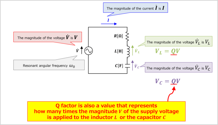
Since the magnitude of the current flowing in the RLC series resonant circuit at the resonant angular frequency \({\omega}_0\) is \(I_{MAX}\), the magnitude \(V_L\) of the voltage across the inductor \(L\) is given by the following equation.
\begin{eqnarray}
V_L={\omega}_0L×I_{MAX}={\omega}_0L×\frac{V}{R}=\frac{{\omega}_0L}{R}×V=Q×V\tag{21}
\end{eqnarray}
Similarly, the magnitude \(V_C\) of the voltage across the capacitor \(C\) is given by the following equation.
\begin{eqnarray}
V_C=\frac{1}{{\omega}_0C}×I_{MAX}=\frac{1}{{\omega}_0C}×\frac{V}{R}=\frac{1}{{\omega}_0CR}×V=Q×V\tag{22}
\end{eqnarray}
Therefore, the Q factor is also a value that represents how many times the magnitude \(V\) of the supply voltage is applied to the inductor \(L\) or the capacitor \(C\). The larger the Q factor, the larger the voltage applied to the inductor \(L\) and the capacitor \(C\).
Summary
This article described the following information about "Q Factor of RLC Series Resonant Circuit".
- What is the Q factor of RLC series resonant circuit?
- Derivation of Q factor of RLC series resonant circuit
- Relationship between "Q factor" and "voltage across the inductor L and capacitor C
Thank you for reading.