Regarding the RC series circuit, this article will explain the information below.
- Power factor \({\cos}{\theta}\) of the RC series Circuit
- Active power \(P\), Reactive power \(Q\), and Apparent power \(S\) of the RC series circuit
[RC Circuit] Power factor & Active, Reactive, and Apparent power
![[RC Series Circuit] Power factor & Active, Reactive, and Apparent power](https://electrical-information.com/wp-content/uploads/2022/07/RC-Series-Circuit-Power-factor-Active-Reactive-and-Apparent-power-1-700x579.png)
Shown in the figure above is an RC series circuit with resistor \(R\) and capacitor \(C\) connected in series.
As an example, the parameters of the RC series circuit are as follows.
- Supply voltage: \({\dot{V}}=200{\;}{\mathrm{[V]}}\)
- Frequency of power supply voltage: \(f=60{\;}{\mathrm{[Hz]}}\)
- Resistance value of resistor: \(R=50\sqrt{3}{\;}{\mathrm{[{\Omega}]}}\)
- Capacitance of capacitor: \(C=53{\;}{\mathrm{[μF]}}\)
The power factor \({\cos}{\theta}\), active power \(P\), reactive power \(Q\), and apparent power \(S\) of the RC series circuit can be obtained by the following procedure (steps 1 to 4).
Procedure
- Calculate the magnitude \(Z\) of the impedance of the RC series circuit
- Calculate the magnitude \(I\) of the current flowing in the RC series circuit
- Calculate the power factor \({\cos}{\theta}\) of the RC series circuit
- Calculate the active power \(P\), reactive power \(Q\), and apparent power \(S\) of the RC series circuit
We will now describe each procedure in turn.
Supplement
There are three types of power in an AC circuit: active power \(P\), reactive power \(Q\), and apparent power \(S\).
- Active power \(P\)
- It is the power consumed by the resistor \(R\) and is also called power consumption. The unit is [W].
- Reactive power \(Q\)
- It is the power that is not consumed by the resistor \(R\). The power that an inductor or capacitor stores or releases is called reactive power. The unit is [var].
- Apparent power \(S\)
- The power is the sum of active power \(P\) and reactive power \(Q\). The unit is [VA].
Calculate the magnitude \(Z\) of the impedance of the RC series circuit
The impedance \({\dot{Z}}_R\) of the resistor \(R\) and the impedance \({\dot{Z}}_C\) of the capacitor \(C\) can be expressed by the following equations, respectively.
\begin{eqnarray}
{\dot{Z}_R}&=&R\tag{1}\\
\\
{\dot{Z}_C}&=&-jX_C=-j\frac{1}{{\omega}C}\tag{2}
\end{eqnarray}
, where \({\omega}\) is the angular frequency, which is equal to \(2{\pi}f\) and \(X_C\) is called capacitive reactance, which is the resistive component of capacitor \(C\).
The capacitive reactance \(X_C\) can be obtained by the following equations.
\begin{eqnarray}
X_C=\frac{1}{{\omega}C}=\frac{1}{2{\pi}fC}&=&\frac{1}{2{\pi}{\;}{\cdot}{\;}60{\;}{\cdot}{\;}53×10^{-6}}\\
\\
&{\approx}&50{\;}{\mathrm{[{\Omega}]}}\tag{3}
\end{eqnarray}
The impedance \({\dot{Z}}\) of the RC series circuit is the sum of the respective impedance and is as follows.
\begin{eqnarray}
{\dot{Z}}&=&{\dot{Z}_R}+{\dot{Z}_C}\\
\\
&=&R-jX_C\\
\\
&=&50\sqrt{3}-j50{\;}{\mathrm{[{\Omega}]}}\tag{4}
\end{eqnarray}
The magnitude \(Z\) of the impedance of the RC series circuit is the absolute value of the impedance \({\dot{Z}}\) in equation (4).
\begin{eqnarray}
Z=|{\dot{Z}}|&=&\sqrt{R^2+{X_C}^2}\\
\\
&=&\sqrt{(50\sqrt{3})^2+50^2}\\
\\
&=&100{\;}{\mathrm{[{\Omega}]}}\tag{5}
\end{eqnarray}
Related article
The following article explains "Impedance of RC Series Circuits" in detail. If you are interested, please check the link below. 続きを見る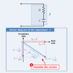
RC Series Circuit (Impedance, Phasor Diagram)
Calculate the magnitude \(I\) of the current flowing in the RC series circuit
The magnitude \(V\) of the supply voltage is the following value.
\begin{eqnarray}
V=|{\dot{V}}|=|200|=200{\;}{\mathrm{[V]}}\tag{6}
\end{eqnarray}
From equations (5) and (6), the magnitude \(I\) of the current flowing in the RC series circuit can be obtained by the following equation
\begin{eqnarray}
I=\frac{V}{Z}=\frac{200}{100}=2{\;}{\mathrm{[A]}}\tag{7}
\end{eqnarray}
Since it is a series circuit, "the magnitude \(I_R\) of the current through the resistor \(R\)" and "the magnitude \(I_C\) of the current through the capacitor \(C\)" are equal to "the magnitude \(I\) of current through the RC series circuit", and the following formula is valid.
\begin{eqnarray}
I=I_R=I_C=2{\;}{\mathrm{[A]}}\tag{8}
\end{eqnarray}
Therefore, "the magnitude \(V_R\) of the voltage across the resistor \(R\)" and "the magnitude \(V_C\) of the voltage across the capacitor \(C\)" can be obtained by the following formula.
\begin{eqnarray}
V_R=I_RR=2{\;}{\cdot}{\;}50\sqrt{3}=100\sqrt{3}{\;}{\mathrm{[V]}}\tag{9}\\
\\
V_C=I_CX_C=2{\;}{\cdot}{\;}50=100{\;}{\mathrm{[V]}}\tag{10}
\end{eqnarray}
Calculate the power factor \({\cos}{\theta}\) of the RC series circuit
The power factor \({\cos}{\theta}\) of an RC series circuit is the ratio of the impedance magnitude \(Z\) to the resistance \(R\) and can be obtained by the following equation
\begin{eqnarray}
{\cos}{\theta}=\frac{R}{Z}=\frac{50\sqrt{3}}{100}=\frac{\sqrt{3}}{2}\tag{11}
\end{eqnarray}
Supplement
The power factor \({\cos}{\theta}\) of the RC series circuit can also be obtained by the ratio of "the magnitude \(V_R\) of the voltage across the resistor \(R\)" to "magnitude \(V\) of the supply voltage". The following equation can be calculated, which is equal to equation (11).
\begin{eqnarray}
{\cos}{\theta}=\frac{V_R}{V}=\frac{100\sqrt{3}}{200}=\frac{\sqrt{3}}{2}\tag{12}
\end{eqnarray}
Calculate the active power \(P\), reactive power \(Q\), and apparent power \(S\) of the RC series circuit
By finding "the magnitude \(V\) of the power supply voltage", "the magnitude \(I\) of the current flowing in the RC series circuit", and "the power factor \({\cos}{\theta}\) of the RC series circuit," the active power \(P\), reactive power \(Q\), and apparent power \(S\) can be calculated.
[RC series circuit] Calculation of apparent power \(S\)
The apparent power \(S\) can be obtained by the following equation.
\begin{eqnarray}
S=VI=200{\;}{\cdot}{\;}2=400{\;}{\mathrm{[VA]}}\tag{13}
\end{eqnarray}
Another solution
The apparent power \(S\) can also be obtained by the following equation. The calculation results show that it is equal to equation (13).
\begin{eqnarray}
S&=&I^2Z=2^2{\;}{\cdot}{\;}100=400{\;}{\mathrm{[VA]}}\tag{14}\\
\\
S&=&\frac{V^2}{Z}=\frac{200^2}{100}=400{\;}{\mathrm{[VA]}}\tag{15}
\end{eqnarray}
[RC series circuit] Calculation of active power \(P\)
The active power \(P\) can be obtained by the following equation
\begin{eqnarray}
P=VI{\cos}{\theta}=200{\;}{\cdot}{\;}2{\;}{\cdot}{\;}\frac{\sqrt{3}}{2}=200\sqrt{3}{\;}{\mathrm{[W]}}\tag{16}
\end{eqnarray}
Another solution
Since the effective power \(P\) is the power consumed by the resistor \(R\), it can also be obtained by the following equation. The calculation results show that it is equal to equation (16).
\begin{eqnarray}
P&=&{I_R}^2R=2^2{\;}{\cdot}{\;}50\sqrt{3}=200\sqrt{3}{\;}{\mathrm{[W]}}\tag{17}\\
\\
P&=&\frac{{V_R}^2}{R}=\frac{(100\sqrt{3})^2}{50\sqrt{3}}=200\sqrt{3}{\;}{\mathrm{[W]}}\tag{18}
\end{eqnarray}
[RC series circuit] Calculation of reactive power \(Q\)
The reactive power \(Q\) can be obtained by the following equation
\begin{eqnarray}
Q=VI{\sin}{\theta}=VI\sqrt{1-{\cos}^2{\theta}}=200{\;}{\cdot}{\;}2{\;}{\cdot}{\;}\sqrt{1-\left(\frac{\sqrt{3}}{2}\right)^2}=200{\;}{\mathrm{[var]}}\tag{19}
\end{eqnarray}
Another solution
Reactive power \(Q\) can also be obtained by the following equation. The calculation results show that it is equal to equation (19).
\begin{eqnarray}
Q&=&{I_L}^2X_C=2^2{\;}{\cdot}{\;}50=200{\;}{\mathrm{[var]}}\tag{20}\\
\\
Q&=&\frac{{V_L}^2}{X_C}=\frac{100^2}{50}=200{\;}{\mathrm{[var]}}\tag{21}
\end{eqnarray}
The power factor \({\cos}{\theta}\) of the RC series circuit can also be obtained by the ratio of "active power \(P\)" to "apparent power \(S\)". The calculation yields the following equation, which is equal to equations (11) and (12).
\begin{eqnarray}
{\cos}{\theta}=\frac{P}{S}=\frac{200\sqrt{3}}{400}=\frac{\sqrt{3}}{2}\tag{22}
\end{eqnarray}
Summary
This article described the following information about the "RC series circuit".
- Power factor \({\cos}{\theta}\) of the RC series Circuit
- Active power \(P\), Reactive power \(Q\), and Apparent power \(S\) of the RC series circuit
Thank you for reading.
Related article
In AC circuits, articles related to power factor \({\cos}{\theta}\), active power \(P\), reactive power \(Q\), and apparent power \(S\) are listed below.
If you are interested, please check the link below.
- RC Series Circuit (Power Factor, Active and Reactive Power)
- RLC Series Circuit (Power Factor, Active and Reactive Power)
- RL Parallel Circuit (Power Factor, Active and Reactive Power)
- RC Parallel Circuit (Power Factor, Active and Reactive Power)
- RLC Parallel Circuit (Power Factor, Active and Reactive Power)