A forward converter is a circuit that converts a DC voltage while keeping the input and output electrically isolated.
This article uses circuit diagrams and waveforms to explain:
- What a forward converter is
- How a forward converter works, its operating modes, its output voltage formula, and its simulation results
What Is a Forward Converter?
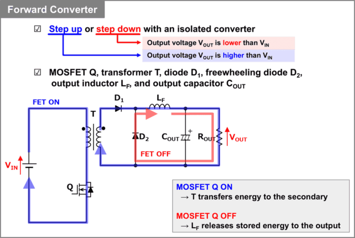
A forward converter is an isolated converter that can step voltage up or down. It consists of a MOSFET \(Q\), a transformer \(T\), a diode \(D_1\), a freewheeling diode \(D_2\), an inductor (choke) \(L_F\), and an output capacitor \(C_{OUT}\). The primary and secondary windings of transformer \(T\) are connected with the same polarity.
Forward converters are used in applications that require higher output power than flyback converters. Compared with a flyback converter, a forward converter requires an additional freewheeling diode \(D_2\) and output inductor \(L_F\).
When MOSFET \(Q\) is on, transformer \(T\) transfers energy to the secondary side. When MOSFET \(Q\) is off, the energy stored in inductor \(L_F\) is delivered to the output as current flows through freewheeling diode \(D_2\). The next section explains this process in more detail.
The forward converter has the following advantages and disadvantages.
Advantages
- It can step voltage up or down, depending on the turns ratio and duty cycle.
- Transformer \(T\) provides electrical isolation between the primary and secondary sides.
- It is suited to applications that require higher output power than a flyback converter.
Disadvantages
- It uses more components than a flyback converter because it requires an additional freewheeling diode \(D_2\) and output inductor \(L_F\).
Note
- A bipolar transistor or another switching device can be used in place of MOSFET \(Q\).
- A freewheeling diode is also called a commutation diode or a flywheel diode.
How a Forward Converter Works
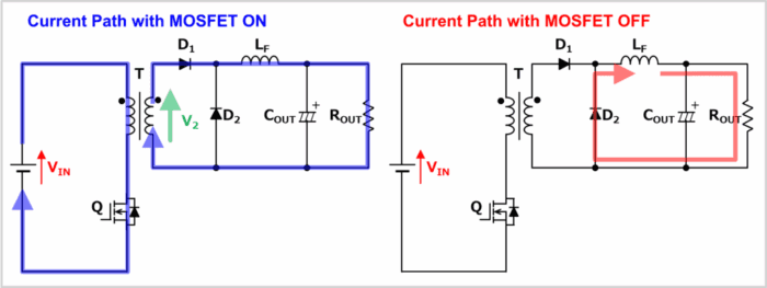
The easiest way to follow the operation of a forward converter is to look at what happens when MOSFET \(Q\) is on and when it is off.
When MOSFET \(Q\) Is On
When MOSFET \(Q\) is on, current flows from the input voltage source \(V_{IN}\) through the primary winding of transformer \(T\) and MOSFET \(Q\). This induces a voltage \(V_2\) on the secondary side of transformer \(T\).
The induced voltage \(V_2\) drives current from the secondary winding of transformer \(T\) through diode \(D_1\) and inductor \(L_F\) to the output circuit, which consists of output capacitor \(C_{OUT}\) and load resistor \(R_{OUT}\). As current flows, inductor \(L_F\) stores energy.
When MOSFET \(Q\) Is Off
When MOSFET \(Q\) turns off, inductor \(L_F\) releases its stored energy and keeps current flowing. The current flows from inductor \(L_F\) through the output circuit (output capacitor \(C_{OUT}\) and load resistor \(R_{OUT}\)) and through freewheeling diode \(D_2\).
In this way, inductor \(L_F\) lets the forward converter supply current continuously to the output circuit.
Forward Converter Output Voltage Formula
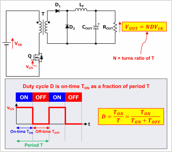
The output voltage \(V_{OUT}\) of a forward converter is given by:
\begin{eqnarray}
V_{OUT}=NDV_{IN}\tag{1}
\end{eqnarray}
In Equation (1), \(N\) is the turns ratio of transformer \(T\). If the primary winding has \(N_1\) turns and the secondary winding has \(N_2\) turns, the turns ratio is:
\begin{eqnarray}
N=\frac{N_2}{N_1}\tag{2}
\end{eqnarray}
In Equation (1), \(D\) is the duty cycle. It is the fraction of each switching period \(T\) during which MOSFET \(Q\) is on. The on-time is \(T_{ON}\), so the duty cycle is:
\begin{eqnarray}
D=\frac{T_{ON}}{T}=\frac{T_{ON}}{T_{ON}+T_{OFF}}=T_{ON}×f_{SW}\tag{3}
\end{eqnarray}
In Equation (3), \(f_{SW}\) is the switching frequency of MOSFET \(Q\), or the number of on-off cycles per second. As Equation (3) shows, the duty cycle \(D\) is less than 1.
Forward vs. Flyback Converter: Circuits and Differences
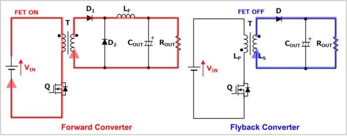
The diagram above shows a forward converter on the left and a flyback converter on the right.
A forward converter delivers energy from the secondary side of the transformer while MOSFET \(Q\) is on.
A flyback converter delivers energy from the secondary side of the transformer while MOSFET \(Q\) is off. It stores that energy in the transformer while MOSFET \(Q\) is on.
Compared with a flyback converter, a forward converter requires an additional freewheeling diode \(D_2\) and inductor \(L_F\). The transformer \(T\) can be smaller because the forward converter transfers energy directly through it during the on-time. Inductor \(L_F\) also reduces output current ripple, allowing the use of a smaller output capacitor \(C_{OUT}\).
The table below summarizes the main differences.
| Forward converter | Flyback converter | |
| Energy transfer | The transformer secondary delivers energy while MOSFET \(Q\) is on. | The transformer secondary delivers energy while MOSFET \(Q\) is off. |
| Total component count | Requires an additional freewheeling diode \(D_2\) and inductor \(L_F\) compared with a flyback converter. | Uses fewer components than a forward converter. |
| Output circuit | An LC filter made up of inductor \(L_F\) and output capacitor \(C_{OUT}\) follows the rectifier. A freewheeling diode \(D_2\) is also required. | Only the output capacitor \(C_{OUT}\) follows the rectifier. |
| Energy storage in the transformer | Energy storage in the transformer is unnecessary, so a smaller transformer can be used. | The transformer stores energy, which calls for a larger transformer and a gap in the core. |
| Transformer winding polarity | The primary and secondary windings have the same polarity. | The primary and secondary windings have opposite polarity. |
| Output capacitance \(C_{OUT}\) | Inductor \(L_F\) can supply current continuously to the output, so a smaller output capacitance can be used. | The circuit has no output inductor \(L_F\). A larger output capacitance is needed to maintain \(V_{OUT}\) while diode \(D\) is off. |
Related Article
For more on the characteristics and operation of a flyback converter, see the following article. 続きを見る
What Is a Flyback Converter? Operation and Equations
Forward vs. Buck Converter: Circuits and Differences
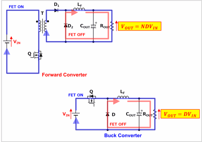
The diagram above shows a forward converter at the upper left and a buck converter at the lower right.
The secondary side of a forward converter operates much like a buck converter.
When MOSFET \(Q\) Is On
In the forward converter, current flows from the input voltage source \(V_{IN}\) through the primary winding of transformer \(T\) and MOSFET \(Q\). This induces a voltage \(V_2\) on the secondary side. The induced voltage drives current from the secondary winding through diode \(D_1\) and inductor \(L_F\) to the output circuit (output capacitor \(C_{OUT}\) and load resistor \(R_{OUT}\)).
In the buck converter, when MOSFET \(Q\) turns on, current flows from the input voltage source \(V_{IN}\) through MOSFET \(Q\) and inductor \(L_F\) to the output circuit (output capacitor \(C_{OUT}\) and load resistor \(R_{OUT}\)).
To see how the two circuits are related, look at the path before inductor \(L_F\). The buck converter uses the input voltage source and MOSFET \(Q\). The forward converter uses the secondary winding of transformer \(T\) and diode \(D_1\) in that part of the path.
When MOSFET \(Q\) Is Off
In the forward converter, when MOSFET \(Q\) turns off, inductor \(L_F\) releases its stored energy and keeps current flowing. The current flows from inductor \(L_F\) through the output circuit (output capacitor \(C_{OUT}\) and load resistor \(R_{OUT}\)) and through freewheeling diode \(D_2\).
In the buck converter, when MOSFET \(Q\) turns off, current flows from inductor \(L_F\) through the output circuit (output capacitor \(C_{OUT}\) and load resistor \(R_{OUT}\)) and through freewheeling diode \(D\).
The forward converter and the buck converter have the same current path through the output circuit while MOSFET \(Q\) is off.
Output Voltage \(V_{OUT}\) Formulas
The two output voltage formulas are closely related. Multiplying the buck converter’s output voltage formula by the transformer turns ratio \(N\) gives the forward converter’s formula.
Buck converter output voltage
\begin{eqnarray}
V_{OUT}=DV_{IN}
\end{eqnarray}
Forward converter output voltage
\begin{eqnarray}
V_{OUT}=NDV_{IN}
\end{eqnarray}
Forward Converter Snubber Circuit (Reset Circuit)
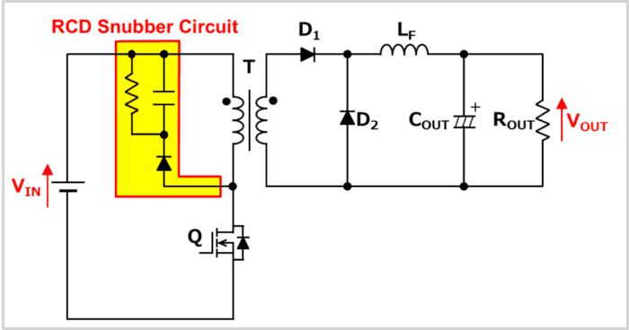
A forward converter magnetizes transformer \(T\) in one direction only. The energy stored in transformer \(T\) must therefore be released while MOSFET \(Q\) is off.
A practical forward converter uses a snubber circuit to reset the transformer.
There are several ways to implement the reset circuit. The diagram above shows one example: an RCD snubber made up of a resistor, a capacitor, and a diode.
Forward Converter Simulation
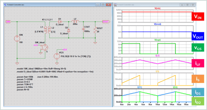
The figure above shows the results of a forward converter simulation in LTspice.
The waveforms on the right are shown in the following order, from top to bottom:
- Input voltage \(V_{IN}\)
- Output voltage \(V_{OUT}\)
- Drive signal \(v_{GS}\) for switch \(S\)
- Current \(i_{LF}\) through inductor \(L_F\)
- Current \(i_S\) through switch \(S\)
- Currents \(i_{D1},i_{D2}\) through diodes \(D_1,D_2\)
The simulation models MOSFET \(Q\) as an ideal switch and diode \(D\) as an ideal diode to ignore their losses.
The input voltage \(V_{IN}\) is set to 100 V, the duty cycle \(D\) of ideal switch \(S\) to 0.5, and the transformer turns ratio \(N\) to 0.1. Substituting these values into Equation (1) gives:
\begin{eqnarray}
V_{OUT}=NDV_{IN}=0.1×0.5×100=5{\mathrm{[V]}}
\end{eqnarray}
The simulation also shows an output voltage \(V_{OUT}\) of 5 V.
Summary
This article covered:
- What a forward converter is
- How a forward converter works, its operating modes, its output voltage formula, and its simulation results
Thanks for reading.