When researching X capacitors, you may come across the markings “X1” and “X2”. What is the difference between them?
X1 and X2 identify the subclasses of X capacitors. This article uses diagrams to explain X capacitor subclasses and answer the following questions:
- What are X capacitor subclasses?
- What is the difference between X1 and X2 capacitors?
- Why does the test voltage decrease as capacitance increases?
- Can an X1 capacitor replace an X2 capacitor?
What Are X Capacitor Subclasses?
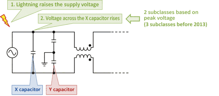
X capacitor subclasses are categories based on factors such as the peak pulse voltage expected in service.
X capacitors are connected across the AC supply lines. Lightning and switching can cause brief high voltages, known as surge voltages, on these lines. Because X capacitors are exposed to these voltages, they must be able to withstand the expected surges.
As explained in more detail below, X capacitors are classified into subclass X1 and subclass X2. When selecting a capacitor, consider the brief high voltages (surge voltages) on the supply lines and choose the subclass according to the expected peak voltage \(V_{PEAK}\).
- If \(V_{PEAK}\) exceeds \(2.5{\mathrm{[kV]}}\) and is no greater than \(4.0{\mathrm{[kV]}}\)
- X1 capacitor is required
- If \(V_{PEAK}\) is no greater than \(2.5{\mathrm{[kV]}}\)
- X2 capacitor is required
Related Article
An X capacitor is connected across the AC supply lines to reduce differential-mode (normal-mode) noise. For more details on X capacitors, see the following article. 続きを見る
What Is an X Capacitor? Function, Selection, and Safety
Differences Between X1 and X2 Capacitors
The X1 and X2 subclasses are defined in the international standard IEC 60384-14. The table below summarizes the classification. Subclass X3 was included in earlier editions but was removed in the fourth edition of IEC 60384-14, published in 2013.
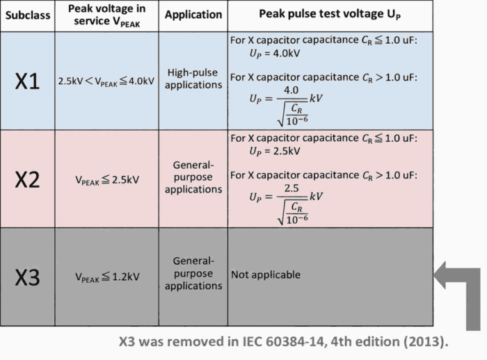
The diagram below shows the subclass ranges. The key is to choose the subclass according to the peak voltage \(V_{PEAK}\) applied from the AC supply. Use an X1 capacitor when \(V_{PEAK}\) exceeds \(2.5{\mathrm{[kV]}}\) and is no greater than \(4.0{\mathrm{[kV]}}\), and use an X2 capacitor when it is no greater than \(2.5{\mathrm{[kV]}}\). The boundary value of \(2.5{\mathrm{[kV]}}\) is included in the X2 range.
【Image】X1 and X2 Peak Voltage Ranges
Points to Check When Replacing an X2 Capacitor with an X1 Capacitor
An X1 capacitor can be used where an X2 capacitor is required, provided it meets the necessary conditions. However, the subclass alone is not enough to determine whether it is a suitable replacement. You must also check the AC voltage rating, capacitance and tolerance, operating temperature, dimensions, and certification conditions. As a basic requirement, the AC voltage rating must be at least as high as the value required for the equipment.
The peak voltage used to classify subclasses represents a brief high voltage. It is different from the AC voltage rating, which specifies the voltage that can be applied continuously.
Why the Test Voltage Decreases as X Capacitor Capacitance Increases
When an X capacitor’s capacitance \(C_R\) exceeds \(1{\mathrm{[\mu F]}}\), the peak pulse voltage \(U_P\) applied during testing decreases. This relationship can be understood by considering the energy stored in the capacitor. When a capacitor with capacitance \(C_R\) is charged to a voltage \(U_P\), its stored energy \(W\) is given by:
\begin{eqnarray}
W= {\frac{1}{2}}{C_R}{U_P}^2
\end{eqnarray}
Here, \(W\) is the stored energy \({\mathrm{[J]}}\), \(C_R\) is the capacitance \({\mathrm{[F]}}\), and \(U_P\) is the peak pulse voltage applied during testing \({\mathrm{[V]}}\).
For capacitances above \(1{\mathrm{[\mu F]}}\), reducing \(U_P\) keeps the energy calculated using this equation constant within each subclass.
The graph below shows how the peak pulse voltage \(U_P\) applied during testing and the energy \(W\) stored in an X capacitor vary with capacitance. The left vertical axis shows peak pulse voltage \({\mathrm{[kV]}}\), and the right vertical axis shows energy \({\mathrm{[J]}}\).
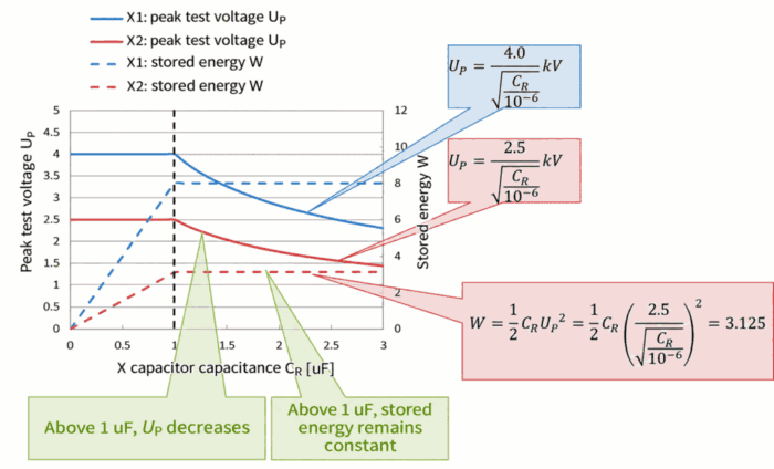
This graph shows that when an X capacitor’s capacitance exceeds \(1{\mathrm{[\mu F]}}\), its stored energy \(W\) remains constant. Above \(1{\mathrm{[\mu F]}}\), the test voltages shown by the solid lines decrease, while the energies shown by the dashed lines remain constant at \(8{\mathrm{[J]}}\) for X1 and \(3.125{\mathrm{[J]}}\) for X2.
Summary
This article explained the following points about X capacitor subclasses:
- X1 is for applications with peak voltages in service above \(2.5{\mathrm{[kV]}}\) and up to \(4.0{\mathrm{[kV]}}\), while X2 is for applications up to \(2.5{\mathrm{[kV]}}\).
- The peak voltage used to classify subclasses is different from the AC voltage rating for continuous operation.
- Above \(1{\mathrm{[\mu F]}}\), the test voltage decreases, while the stored energy remains constant within each subclass.
- When replacing an X2 capacitor with an X1 capacitor, you must also check factors such as voltage rating, capacitance, and certification conditions.
Thank you for reading.