When resistors are connected in series, how many volts appear across each resistor? The rule that lets us calculate these voltages from the ratio of the resistance values is the voltage divider rule.
This article explains the voltage divider rule with diagrams, covering the following topics.
- What the voltage divider rule is
- Voltage divider formulas, their derivation, and worked examples
- The difference between the voltage divider rule and the current divider formula
What Is the Voltage Divider Rule?
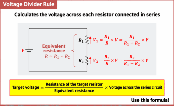
The voltage divider rule is a rule for calculating the voltage across each resistor when resistors are connected in series.
The diagram above shows resistors \(R_1{\mathrm{[{\Omega}]}}\) and \(R_2{\mathrm{[{\Omega}]}}\) connected in series, with a supply voltage \(V{\mathrm{[V]}}\) applied across the circuit.
Let \(R{\mathrm{[{\Omega}]}}\) be the equivalent resistance of resistors \(R_1{\mathrm{[{\Omega}]}}\) and \(R_2{\mathrm{[{\Omega}]}}\). The voltage \(V_1{\mathrm{[V]}}\) across resistor \(R_1{\mathrm{[{\Omega}]}}\) and the voltage \(V_2{\mathrm{[V]}}\) across resistor \(R_2{\mathrm{[{\Omega}]}}\) are given by the following equations.
\begin{eqnarray}
V_1&=&\frac{R_1}{R}×V=\frac{R_1}{R_1+R_2}×V{\mathrm{[V]}}\tag{1}\\
\\
V_2&=&\frac{R_2}{R}×V=\frac{R_2}{R_1+R_2}×V{\mathrm{[V]}}\tag{2}
\end{eqnarray}
Equations (1) and (2) are the voltage divider formulas. The numerator contains the resistance of the resistor whose voltage you want to calculate.
Resistors \(R_1\) and \(R_2\) divide the voltage \(V\) into \(V_1\) and \(V_2\). This is called voltage division.
In words, equations (1) and (2) can be expressed as follows.
\begin{eqnarray}
\mbox{Target voltage}=\frac{\mbox{Resistance of the target resistor}}{\mbox{Equivalent resistance}}×\mbox{Voltage across the series circuit}\tag{3}
\end{eqnarray}
Equivalent resistance is the resistance of a single resistor that can replace multiple resistors. In equations (1) and (2), \(R_1\) and \(R_2\) are the individual resistance values, and \(R\) is the equivalent resistance of the entire series circuit.
Derivation of the Voltage Divider Formulas
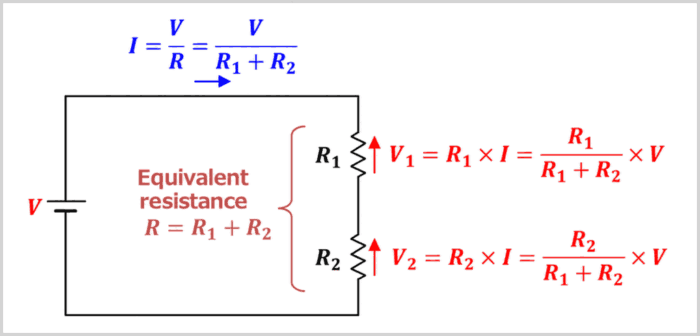
Let us derive equations (1) and (2).
The diagram above shows resistors \(R_1{\mathrm{[{\Omega}]}}\) and \(R_2{\mathrm{[{\Omega}]}}\) connected in series, with a supply voltage \(V{\mathrm{[V]}}\) applied across the circuit.
The equivalent resistance \(R{\mathrm{[{\Omega}]}}\) of resistors \(R_1{\mathrm{[{\Omega}]}}\) and \(R_2{\mathrm{[{\Omega}]}}\) in this circuit is given by the following equation.
\begin{eqnarray}
R=R_1+R_2{\mathrm{[{\Omega}]}}\tag{4}
\end{eqnarray}
Therefore, using Ohm's law, the current \(I{\mathrm{[A]}}\) flowing through this circuit is given by the following equation.
\begin{eqnarray}
I=\frac{V}{R}=\frac{V}{R_1+R_2}{\mathrm{[A]}}\tag{5}
\end{eqnarray}
Also, using Ohm's law, the voltage \(V_1{\mathrm{[V]}}\) across resistor \(R_1{\mathrm{[{\Omega}]}}\) and the voltage \(V_2{\mathrm{[V]}}\) across resistor \(R_2{\mathrm{[{\Omega}]}}\) are given by the following equations.
\begin{eqnarray}
V_1&=&R_1×I{\mathrm{[V]}}\tag{6}\\
\\
V_2&=&R_2×I{\mathrm{[V]}}\tag{7}
\end{eqnarray}
Substituting equation (5) into equations (6) and (7) gives the following expressions, which yield equations (1) and (2).
\begin{eqnarray}
V_1&=&R_1×\frac{V}{R_1+R_2}\\
\\
&=&\frac{R_1}{R_1+R_2}×V{\mathrm{[V]}}\tag{8}\\
\\
V_2&=&R_2×\frac{V}{R_1+R_2}\\
\\
&=&\frac{R_2}{R_1+R_2}×V{\mathrm{[V]}}\tag{9}
\end{eqnarray}
Thus, we can find the voltage across each resistor by first calculating the current through the entire circuit and then multiplying that current by each resistance value.
Voltage Divider Example (Two Resistors in Series)
Example
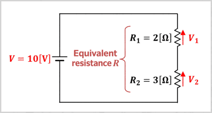
In the circuit shown above, the supply voltage \(V\) is \(10{\mathrm{[V]}}\), resistor \(R_1\) is \(2{\mathrm{[{\Omega}]}}\), and resistor \(R_2\) is \(3{\mathrm{[{\Omega}]}}\). Find the following:
- What is the equivalent resistance \(R\) of resistors \(R_1\) and \(R_2\), in \({\mathrm{{\Omega}}}\)?
- What is the voltage \(V_1\) across resistor \(R_1\), in \({\mathrm{V}}\)?
- What is the voltage \(V_2\) across resistor \(R_2\), in \({\mathrm{V}}\)?
The equivalent resistance \(R{\mathrm{[{\Omega}]}}\) of resistors \(R_1\) and \(R_2\) is given by the following equation.
\begin{eqnarray}
R=R_1+R_2=2+3=5{\mathrm{[{\Omega}]}}\tag{10}
\end{eqnarray}
Therefore, the voltage \(V_1{\mathrm{[V]}}\) across resistor \(R_1\) is calculated as follows.
\begin{eqnarray}
\mbox{Target voltage}&=&\frac{\mbox{Resistance of the target resistor}}{\mbox{Equivalent resistance}}×\mbox{Voltage across the series circuit}\\
\\
{\Leftrightarrow}V_1&=&\frac{R_1}{R}×V\\
\\
&=&\frac{2}{5}×10\\
\\
&=&4{\mathrm{[V]}}\tag{11}
\end{eqnarray}
Similarly, the voltage \(V_2{\mathrm{[V]}}\) across resistor \(R_2\) is calculated as follows.
\begin{eqnarray}
\mbox{Target voltage}&=&\frac{\mbox{Resistance of the target resistor}}{\mbox{Equivalent resistance}}×\mbox{Voltage across the series circuit}\\
\\
{\Leftrightarrow}V_2&=&\frac{R_2}{R}×V\\
\\
&=&\frac{3}{5}×10\\
\\
&=&6{\mathrm{[V]}}\tag{12}
\end{eqnarray}
The answers are an equivalent resistance of \(5{\mathrm{[\Omega]}}\), \(V_1\) of \(4{\mathrm{[V]}}\), and \(V_2\) of \(6{\mathrm{[V]}}\). Resistor \(R_2\), which has the higher resistance, has the larger voltage across it. We can also confirm that the two voltages add up to the supply voltage of \(10{\mathrm{[V]}}\).
Voltage Divider Rule: Three Resistors in Series
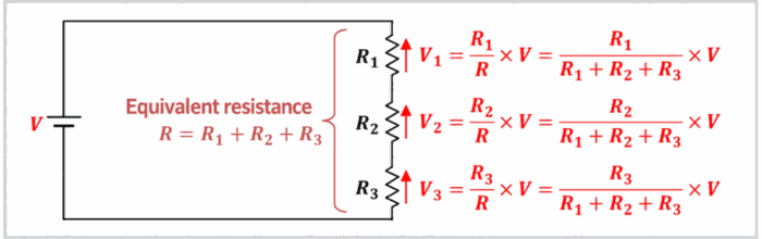
The diagram above shows resistors \(R_1{\mathrm{[{\Omega}]}}\), \(R_2{\mathrm{[{\Omega}]}}\), and \(R_3{\mathrm{[{\Omega}]}}\) connected in series, with a supply voltage \(V{\mathrm{[V]}}\) applied across the circuit.
Let \(R{\mathrm{[{\Omega}]}}\) be the equivalent resistance of resistors \(R_1{\mathrm{[{\Omega}]}}\), \(R_2{\mathrm{[{\Omega}]}}\), and \(R_3{\mathrm{[{\Omega}]}}\). The voltages \(V_1{\mathrm{[V]}}\), \(V_2{\mathrm{[V]}}\), and \(V_3{\mathrm{[V]}}\) across resistors \(R_1{\mathrm{[{\Omega}]}}\), \(R_2{\mathrm{[{\Omega}]}}\), and \(R_3{\mathrm{[{\Omega}]}}\), respectively, are given by the following equations.
\begin{eqnarray}
V_1&=&\frac{R_1}{R}×V=\frac{R_1}{R_1+R_2+R_3}×V{\mathrm{[V]}}\tag{13}\\
\\
V_2&=&\frac{R_2}{R}×V=\frac{R_2}{R_1+R_2+R_3}×V{\mathrm{[V]}}\tag{14}\\
\\
V_3&=&\frac{R_3}{R}×V=\frac{R_3}{R_1+R_2+R_3}×V{\mathrm{[V]}}\tag{15}
\end{eqnarray}
Voltage Divider Example (Three Resistors in Series)
Example
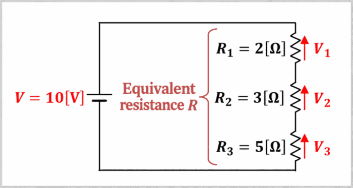
In the circuit shown above, the supply voltage \(V\) is \(10{\mathrm{[V]}}\), resistor \(R_1\) is \(2{\mathrm{[{\Omega}]}}\), resistor \(R_2\) is \(3{\mathrm{[{\Omega}]}}\), and resistor \(R_3\) is \(5{\mathrm{[{\Omega}]}}\). Find the following:
- What is the equivalent resistance \(R\) of resistors \(R_1\), \(R_2\), and \(R_3\), in \({\mathrm{{\Omega}}}\)?
- What is the voltage \(V_1\) across resistor \(R_1\), in \({\mathrm{V}}\)?
- What is the voltage \(V_2\) across resistor \(R_2\), in \({\mathrm{V}}\)?
- What is the voltage \(V_3\) across resistor \(R_3\), in \({\mathrm{V}}\)?
The equivalent resistance \(R{\mathrm{[{\Omega}]}}\) of resistors \(R_1\), \(R_2\), and \(R_3\) is given by the following equation.
\begin{eqnarray}
R=R_1+R_2+R_3=2+3+5=10{\mathrm{[{\Omega}]}}\tag{16}
\end{eqnarray}
Therefore, the voltage \(V_1{\mathrm{[V]}}\) across resistor \(R_1\) is calculated as follows.
\begin{eqnarray}
\mbox{Target voltage}&=&\frac{\mbox{Resistance of the target resistor}}{\mbox{Equivalent resistance}}×\mbox{Voltage across the series circuit}\\
\\
{\Leftrightarrow}V_1&=&\frac{R_1}{R}×V\\
\\
&=&\frac{2}{10}×10\\
\\
&=&2{\mathrm{[V]}}\tag{17}
\end{eqnarray}
Similarly, the voltage \(V_2{\mathrm{[V]}}\) across resistor \(R_2\) is calculated as follows.
\begin{eqnarray}
\mbox{Target voltage}&=&\frac{\mbox{Resistance of the target resistor}}{\mbox{Equivalent resistance}}×\mbox{Voltage across the series circuit}\\
\\
{\Leftrightarrow}V_2&=&\frac{R_2}{R}×V\\
\\
&=&\frac{3}{10}×10\\
\\
&=&3{\mathrm{[V]}}\tag{18}
\end{eqnarray}
Similarly, the voltage \(V_3{\mathrm{[V]}}\) across resistor \(R_3\) is calculated as follows.
\begin{eqnarray}
\mbox{Target voltage}&=&\frac{\mbox{Resistance of the target resistor}}{\mbox{Equivalent resistance}}×\mbox{Voltage across the series circuit}\\
\\
{\Leftrightarrow}V_3&=&\frac{R_3}{R}×V\\
\\
&=&\frac{5}{10}×10\\
\\
&=&5{\mathrm{[V]}}\tag{19}
\end{eqnarray}
The answers are an equivalent resistance of \(10{\mathrm{[\Omega]}}\) and voltages of \(2{\mathrm{[V]}}\), \(3{\mathrm{[V]}}\), and \(5{\mathrm{[V]}}\), respectively. With three resistors, we can use the same method by putting the equivalent resistance of the entire circuit in the denominator. The three voltages add up to the supply voltage of \(10{\mathrm{[V]}}\).
Voltage Divider Rule: N Resistors in Series
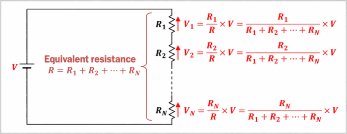
The diagram above shows resistors \(R_1{\mathrm{[{\Omega}]}}\), \(R_2{\mathrm{[{\Omega}]}}\), ..., \(R_N{\mathrm{[{\Omega}]}}\) connected in series, with a supply voltage \(V{\mathrm{[V]}}\) applied across the circuit.
Let \(R{\mathrm{[{\Omega}]}}\) be the equivalent resistance of resistors \(R_1{\mathrm{[{\Omega}]}}\) through \(R_N{\mathrm{[{\Omega}]}}\). The voltages \(V_1{\mathrm{[V]}}\), \(V_2{\mathrm{[V]}}\), ..., \(V_N{\mathrm{[V]}}\) across resistors \(R_1{\mathrm{[{\Omega}]}}\), \(R_2{\mathrm{[{\Omega}]}}\), ..., \(R_N{\mathrm{[{\Omega}]}}\), respectively, are given by the following equations.
\begin{eqnarray}
V_1&=&\frac{R_1}{R}×V=\frac{R_1}{R_1+R_2+{\;}{\cdots}{\;}+R_N}×V{\mathrm{[V]}}\tag{20}\\
\\
V_2&=&\frac{R_2}{R}×V=\frac{R_2}{R_1+R_2+{\;}{\cdots}{\;}+R_N}×V{\mathrm{[V]}}\tag{21}\\
\\
V_N&=&\frac{R_N}{R}×V=\frac{R_N}{R_1+R_2+{\;}{\cdots}{\;}+R_N}×V{\mathrm{[V]}}\tag{22}
\end{eqnarray}
Here, \(N\) is the number of resistors connected in series. Regardless of the number of resistors, the denominator contains the sum of all the resistance values, and the numerator contains the resistance of the resistor whose voltage you want to calculate. The voltages across all the resistors add up to the voltage \(V\) across the entire series circuit.
Difference Between the Voltage Divider Rule and the Current Divider Rule
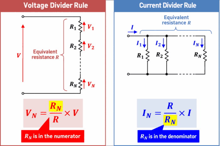
The formulas for the voltage divider rule and the current divider rule are very similar.
The voltage divider rule calculates voltages in a series circuit, while the current divider rule calculates currents in a parallel circuit. Although the formulas are similar, they apply to different circuit connections and calculate different quantities.
Voltage Divider Rule
The voltage divider rule is a rule for calculating the voltage across each resistor when resistors are connected in series.
Let \(R{\mathrm{[{\Omega}]}}\) be the equivalent resistance of the resistors connected in series, and let \(V{\mathrm{[V]}}\) be the voltage across the series circuit. The voltage \(V_N{\mathrm{[V]}}\) across resistor \(R_N{\mathrm{[{\Omega}]}}\) is given by the following equation.
\begin{eqnarray}
V_N=\frac{R_N}{R}×V{\mathrm{[V]}}\tag{23}
\end{eqnarray}
Current Divider Rule
The current divider rule is a rule for calculating the current through each resistor when resistors are connected in parallel.
Let \(R{\mathrm{[{\Omega}]}}\) be the equivalent resistance of the resistors connected in parallel, and let \(I{\mathrm{[A]}}\) be the current entering the parallel circuit. The current \(I_N{\mathrm{[A]}}\) through resistor \(R_N{\mathrm{[{\Omega}]}}\) is given by the following equation.
\begin{eqnarray}
I_N=\frac{R}{R_N}×I{\mathrm{[A]}}\tag{24}
\end{eqnarray}
The symbol \(R\) in these two equations does not represent the same equivalent resistance. In equation (23), \(R\) is the equivalent resistance of the series circuit; in equation (24), it is the equivalent resistance of the parallel circuit.
Equations (23) and (24) look similar. Note that resistance \(R_N{\mathrm{[{\Omega}]}}\) is in the numerator in the voltage divider rule, whereas resistance \(R_N{\mathrm{[{\Omega}]}}\) is in the denominator in the current divider rule.
Related Article
For more details on the current divider rule, see the following article. 続きを見る
Current Divider Rule: Formula, Derivation, and Examples
Summary
This article explained the following key points about the voltage divider rule.
- The voltage divider rule calculates the voltage across each resistor in a series circuit.
- The voltage across each resistor is found by multiplying the supply voltage by the resistance of that resistor divided by the equivalent resistance of the entire series circuit.
- Because the same current flows through all resistors in a series circuit, a resistor with a higher resistance has a larger voltage across it.
- Voltage division is used to calculate voltages in a series circuit, while current division is used to calculate currents in a parallel circuit.
Thank you for reading.