When studying electric circuits, you may come across the terms “voltage source” and “current source.” The key to understanding the difference is whether the source maintains a constant voltage or a constant current as the load changes.
This article explains the following topics using diagrams and equations.
- Differences between voltage sources and current sources
- Conditions for voltage sources and current sources to be equivalent
- Source transformation methods and calculation examples
Differences Between Voltage Sources and Current Sources
The diagram below compares voltage source and current source models that include internal resistance.
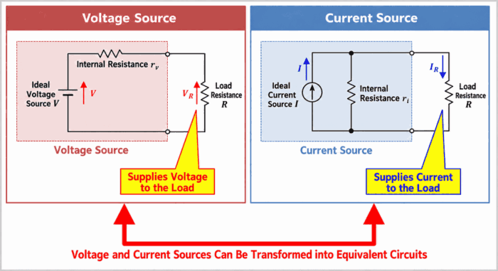
A voltage source supplies voltage to a load. Its basic equivalent circuit consists of an ideal voltage source \(V\) (a source that provides a constant voltage) in series with an internal resistance \(r_v\).
A current source supplies current to a load. Its basic equivalent circuit consists of an ideal current source \(I\) (a source that provides a constant current) in parallel with an internal resistance \(r_i\).
These voltage sources and current sources can be transformed into equivalent circuits when certain conditions are met. Let us now look at how to perform this transformation.
Related Articles
The following articles explain voltage sources and current sources in more detail. Follow the links below if you would like to learn more.
続きを見る
What Is a Voltage Source? Characteristics, Symbols, and Internal Resistance
続きを見る
What Is a Current Source? Characteristics, Symbols, and Internal Resistance
How to Transform Voltage Sources and Current Sources
To transform a voltage source into a current source, or vice versa, we first need to determine the conditions under which a voltage source and a current source are equivalent.
Conditions for Voltage Sources and Current Sources to Be Equivalent
The diagram below shows both models connected to the same load resistance, along with the conditions for equivalence.
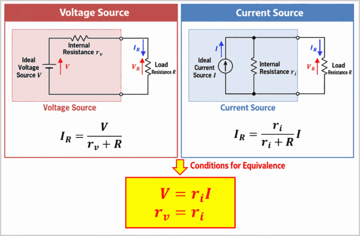
A voltage source and a current source are equivalent when connecting the same load resistance \(R\) produces the same current \(I_R\) through the load resistance \(R\) before and after the transformation. If the current \(I_R\) through the load resistance \(R\) is the same, the voltage \(V_R\) across the load resistance \(R\) is also the same.
When a load resistance \(R\) is connected to the voltage source, the current \(I_R\) is given by the following equation.
In the voltage source model, the internal resistance \(r_v\) and the load resistance \(R\) are in series. The current is therefore found by dividing the voltage \(V\) by the sum of these resistances.
\begin{eqnarray}
I_R=\frac{V}{r_v+R}\tag{1}
\end{eqnarray}
When a load resistance \(R\) is connected to the current source, the current \(I_R\) is given by the following equation.
In the current source model, the ideal source current \(I\) divides between the internal resistance \(r_i\) and the load resistance \(R\). Equation (2) gives the portion of this current that flows through the load.
\begin{eqnarray}
I_R=\frac{r_i}{r_i+R}I\tag{2}
\end{eqnarray}
Here, \(V\) is the ideal voltage source voltage \({\mathrm{[V]}}\), \(I\) is the ideal current source current \({\mathrm{[A]}}\), \(r_v\) and \(r_i\) are the respective internal resistances \({\mathrm{[Ω]}}\), \(R\) is the load resistance \({\mathrm{[Ω]}}\), and \(I_R\) is the load current \({\mathrm{[A]}}\). For the voltage source and current source to be equivalent, equations (1) and (2) must be equal. The conditions are as follows.
Conditions for Equivalent Voltage and Current Sources
\begin{eqnarray}
V&=&r_iI\tag{3}\\
r_v&=&r_i\tag{4}
\end{eqnarray}
Equation (3) describes the relationship between voltage and current, while equation (4) shows that the internal resistance retains the same value after transformation. These conditions allow us to transform a voltage source into an equivalent current source, or vice versa. Let us try both transformations.
How to Transform a Voltage Source into a Current Source
The diagram below shows a voltage source transformed into a current source. The resistor changes from a series connection to a parallel connection.
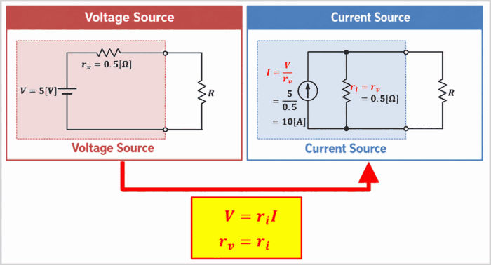
We transform a voltage source consisting of an ideal voltage source \(V\) (a source that provides a constant voltage) in series with an internal resistance \(r_v\) into a current source.
For reference, the conditions for voltage sources and current sources to be equivalent are repeated below.
Conditions for Equivalent Voltage and Current Sources
\begin{eqnarray}
V&=&r_iI\tag{3}\\
r_v&=&r_i\tag{4}
\end{eqnarray}
Using these conditions, the ideal current source \(I\) and internal resistance \(r_i\) after transforming the voltage source into a current source are given by the following equations.
\begin{eqnarray}
I&=&\frac{V}{r_v}\tag{5}\\
\\
r_i&=&r_v\tag{6}
\end{eqnarray}
The conditions for voltage sources and current sources to be equivalent therefore allow us to transform a voltage source into a current source.
For example, suppose the ideal voltage source \(V\) has a voltage of \(V=5{\mathrm{[V]}}\), and the voltage source internal resistance \(r_v\) is \(r_v=0.5{\mathrm{[Ω]}}\). After transformation into a current source, the ideal current source \(I\) and internal resistance \(r_i\) have the following values.
\begin{eqnarray}
I&=&\frac{V}{r_v}=\frac{5}{0.5}=10{\mathrm{[A]}}\tag{7}\\
\\
r_i&=&r_v=0.5{\mathrm{[Ω]}}\tag{8}
\end{eqnarray}
How to Transform a Current Source into a Voltage Source
The diagram below shows a current source transformed into a voltage source. The resistor changes from a parallel connection to a series connection.
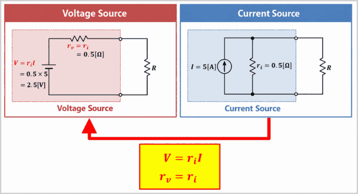
We transform a current source consisting of an ideal current source \(I\) (a source that provides a constant current) in parallel with an internal resistance \(r_i\) into a voltage source.
For reference, the conditions for voltage sources and current sources to be equivalent are repeated below.
Conditions for Equivalent Voltage and Current Sources
\begin{eqnarray}
V&=&r_iI\tag{3}\\
r_v&=&r_i\tag{4}
\end{eqnarray}
Equations (3) and (4) give the ideal voltage source \(V\) and internal resistance \(r_v\) after transforming the current source into a voltage source.
The conditions for voltage sources and current sources to be equivalent therefore allow us to transform a current source into a voltage source.
For example, suppose the ideal current source \(I\) has a current of \(I=5{\mathrm{[A]}}\), and the current source internal resistance \(r_i\) is \(r_i=0.5{\mathrm{[Ω]}}\). After transformation into a voltage source, the ideal voltage source \(V\) and internal resistance \(r_v\) have the following values.
\begin{eqnarray}
V&=&r_iI=0.5×5=2.5{\mathrm{[V]}}\tag{9}\\
\\
r_v&=&r_i=0.5{\mathrm{[Ω]}}\tag{10}
\end{eqnarray}
Note
The source orientation must also be matched during transformation. In the diagrams in this article, the ideal current source arrow points toward the positive terminal side of the voltage source. Reversing this direction would make the sources non-equivalent.
Worked Example: Voltage Sources and Current Sources
Worked Example
Consider the circuit below, in which two voltage sources, each with an internal resistance, are connected in parallel.
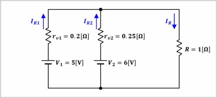
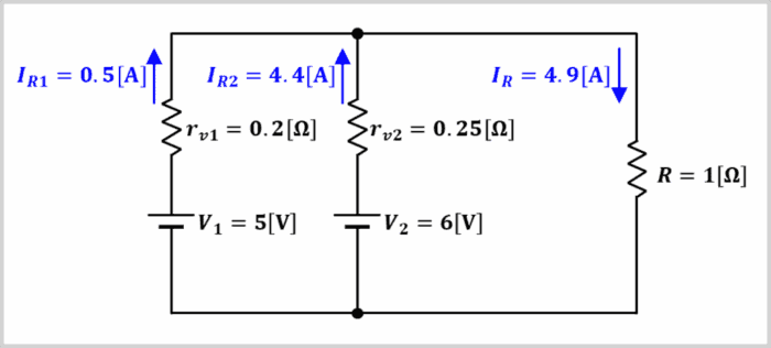
In the circuit shown above, the voltage sources \(V_1=5{\mathrm{[V]}}(r_{v1}=0.2{\mathrm{[Ω]}})\) and \(V_2=6{\mathrm{[V]}}(r_{v2}=0.25{\mathrm{[Ω]}})\) are connected in parallel, with a load resistance of \(R=1{\mathrm{[Ω]}}\).
For this circuit, consider the following currents:
- The current \(I_{R1}\) flowing from voltage source \(V_1\) toward the load
- The current \(I_{R2}\) flowing from voltage source \(V_2\) toward the load
- The current \(I_R\) through the load resistance \(R\)
Let us calculate these currents.
In the diagram, the positive directions for \(I_{R1}\) and \(I_{R2}\) are from the voltage sources toward the upper node. The positive direction for \(I_R\) is downward through the load resistor. We calculate the currents using the following steps.
Steps to Calculate the Currents
- Transform the voltage sources into current sources
- Calculate the current through each resistor
- Use Kirchhoff’s law to calculate the source currents
Transform the Voltage Sources into Current Sources
The diagram below shows the circuit after each of the two voltage sources in the example has been transformed into a current source.
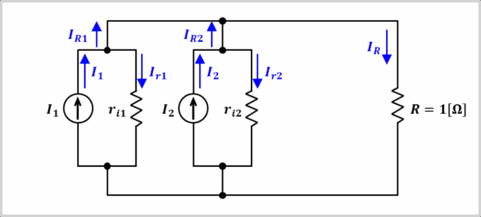
Applying equation (5) to each voltage source gives the following currents for the ideal current sources \(I_1\) and \(I_2\) after transformation.
\begin{eqnarray}
I_1&=&\frac{V_1}{r_{v1}}=\frac{5}{0.2}=25{\mathrm{[A]}}\tag{11}\\
\\
I_2&=&\frac{V_2}{r_{v2}}=\frac{6}{0.25}=24{\mathrm{[A]}}\tag{12}
\end{eqnarray}
The two ideal current sources supply current in the same direction. The combined current \(I\) from the ideal current sources \(I_1\) and \(I_2\) is therefore found by adding their currents.
\begin{eqnarray}
I&=&I_1+I_2=25+24=49{\mathrm{[A]}}\tag{13}
\end{eqnarray}
The current source internal resistances \(r_{i1}\) and \(r_{i2}\) have the following values.
\begin{eqnarray}
r_{i1}&=&r_{v1}=0.2{\mathrm{[Ω]}}\tag{14}\\
\\
r_{i2}&=&r_{v2}=0.25{\mathrm{[Ω]}}\tag{15}
\end{eqnarray}
Calculate the Current Through Each Resistor
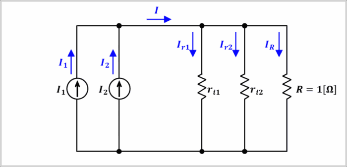
Resistors connected in parallel have the same voltage across them, so a smaller resistance carries a larger current. The quantity that describes how easily current flows is conductance (the reciprocal of resistance), measured in \({\mathrm{[S]}}\) (siemens). For resistors connected in parallel, current divides in proportion to the conductance of each resistor. The currents through the resistors are therefore as follows.
\begin{eqnarray}
I_{r1}&=&\frac{\displaystyle\frac{1}{r_{i1}}}{\displaystyle\frac{1}{r_{i1}}+\displaystyle\frac{1}{r_{i2}}+\displaystyle\frac{1}{R}}×I\\
\\
&=&\frac{\displaystyle\frac{1}{0.2}}{\displaystyle\frac{1}{0.2}+\displaystyle\frac{1}{0.25}+\displaystyle\frac{1}{1}}×49\\
\\
&=&\frac{5}{5+4+1}×49\\
\\
&=&24.5{\mathrm{[A]}}\tag{16}\\
\\
I_{r2}&=&\frac{\displaystyle\frac{1}{r_{i2}}}{\displaystyle\frac{1}{r_{i1}}+\displaystyle\frac{1}{r_{i2}}+\displaystyle\frac{1}{R}}×I\\
\\
&=&\frac{\displaystyle\frac{1}{0.25}}{\displaystyle\frac{1}{0.2}+\displaystyle\frac{1}{0.25}+\displaystyle\frac{1}{1}}×49\\
\\
&=&\frac{4}{5+4+1}×49\\
\\
&=&19.6{\mathrm{[A]}}\tag{17}\\
\\
I_{R}&=&\frac{\displaystyle\frac{1}{R}}{\displaystyle\frac{1}{r_{i1}}+\displaystyle\frac{1}{r_{i2}}+\displaystyle\frac{1}{R}}×I\\
\\
&=&\frac{\displaystyle\frac{1}{1}}{\displaystyle\frac{1}{0.2}+\displaystyle\frac{1}{0.25}+\displaystyle\frac{1}{1}}×49\\
\\
&=&\frac{1}{5+4+1}×49\\
\\
&=&4.9{\mathrm{[A]}}\tag{18}
\end{eqnarray}
Use Kirchhoff’s Law to Calculate the Source Currents
The diagram below shows the relationship between the current flowing from each source toward the load and the current diverted through its internal resistance.
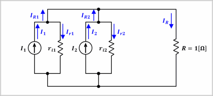
Kirchhoff’s current law states that the total current entering a node equals the total current leaving it. Subtracting the current through each parallel internal resistance from the current supplied by its ideal current source gives the currents \(I_{R1}\) and \(I_{R2}\) flowing from the original voltage sources toward the load.
\begin{eqnarray}
I_{R1}&=I_1-I_{r1}=25-24.5=0.5{\mathrm{[A]}}\tag{19}\\
\\
I_{R2}&=I_2-I_{r2}=24-19.6=4.4{\mathrm{[A]}}\tag{20}
\end{eqnarray}
The resulting current \(I_{R1}\) through voltage source \(V_1\), current \(I_{R2}\) through voltage source \(V_2\), and current \(I_R\) through the load resistance \(R\) are shown in the diagram below.
Summary
This article covered the following points about voltage sources and current sources.
- An ideal voltage source maintains a constant voltage, while an ideal current source maintains a constant current, regardless of the load
- In models that include internal resistance, the resistance is connected in series with a voltage source and in parallel with a current source
- Voltage sources and current sources can be transformed into equivalent circuits when \(V=r_iI\) and \(r_v=r_i\) are satisfied
Thank you for reading.