When studying electric circuits, you may come across the term “current source.”
A current source supplies current to a circuit. However, ideal and practical current sources differ in how their output current behaves when a load is connected.
For example, an ideal current source maintains a constant output current even when the load resistance \(R\) changes. In contrast, when a practical current source is modeled using an equivalent circuit with internal resistance, its output current decreases as the load resistance increases.
This article explains the following topics about current sources:
- What Is a Current Source?
- Load Current When the Current Source Internal Resistance r Is Infinite
- Load Current with Current Source Internal Resistance r
- Current Source Symbols
- Voltage Across a Current Source
We use diagrams to make these topics easy to understand. We hope you find this article helpful.
What Is a Current Source?
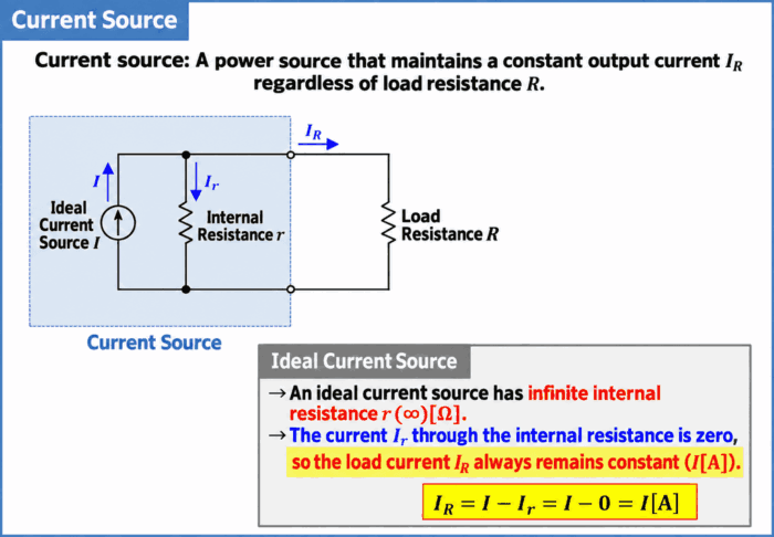
A current source is a power source that maintains a constant output current \(I_R\) regardless of the load resistance \(R\). In particular, an ideal power source that maintains a constant output current regardless of the load is called an “ideal current source.”
A practical current source can be represented by a basic equivalent circuit consisting of an “ideal current source \(I\) (a power source that supplies a constant current)” connected in parallel with an “internal resistance \(r\).”
A current source with an infinite internal resistance \(r\) (\(\infty{\mathrm{[\Omega]}}\)) is an ideal current source. In this case, the current \(I_r\) through the internal resistance \(r\) is \(0{\mathrm{[A]}}\), so the current \(I_R\) through the load resistance \(R\) is expressed by the following equation.
\begin{eqnarray}
I&=&I_r+I_R\\
\\
{\Leftrightarrow}I_R&=&I-I_r\\
\\
&=&I-0\\
\\
&=&I{\mathrm{[A]}}\tag{1}
\end{eqnarray}
Here, \(I\) is the ideal current source current \({\mathrm{[A]}}\), \(I_r\) is the current through the internal resistance \({\mathrm{[A]}}\), and \(I_R\) is the current through the load resistance \({\mathrm{[A]}}\).
Equation (1) does not contain the load resistance \(R\). Therefore, for an ideal current source, the current \(I_R\) through the load resistance \(R\) always remains constant (\(I{\mathrm{[A]}}\)), regardless of the value of \(R\).
Here, we consider current sources that supply a constant DC current. For an ideal AC current source, the current changes over time, but its waveform is independent of the load.
Key Points
- An ideal current source has an internal resistance \(r\) that is infinite (\(\infty{\mathrm{[\Omega]}}\)).
- In this case, the current \(I_R\) through the load resistance \(R\) always remains constant, regardless of the value of \(R\).
Next, let us consider how the current \(I_R\) through the load resistance \(R\) behaves when the internal resistance \(r\) is taken into account.
Load Current with Current Source Internal Resistance r
The following diagram shows the equivalent circuit of a current source with internal resistance \(r\), along with how the output current changes with the load resistance \(R\).
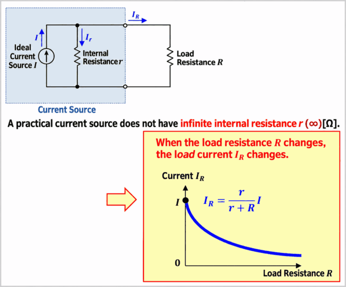
For a practical current source, the internal resistance \(r\) cannot always be treated as infinite (\(\infty{\mathrm{[\Omega]}}\)). In this case, the current supplied by the “ideal current source \(I\) (a power source that supplies a constant current)” divides between the internal resistance \(r\) and the load resistance \(R\). The current \(I_R\) through the load resistance \(R\) is therefore given by the following equation.
\begin{eqnarray}
I_R=\frac{r}{r+R}I{\mathrm{[A]}}\tag{2}
\end{eqnarray}
Here, \(I\) is the ideal current source current \({\mathrm{[A]}}\), \(r\) is the current source internal resistance \({\mathrm{[\Omega]}}\), \(R\) is the load resistance \({\mathrm{[\Omega]}}\), and \(I_R\) is the current through the load resistance \({\mathrm{[A]}}\).
Equation (2) contains the load resistance \(R\). Therefore, when the value of the load resistance \(R\) changes, the current \(I_R\) through it also changes. As the load resistance \(R\) increases, the terminal voltage rises, and the current \(I_r\) through the internal resistance \(r\) also increases.
For an ideal current source, the internal resistance \(r\) is infinite (\(\infty{\mathrm{[\Omega]}}\)), so the current \(I_R\) through the load resistance \(R\) can be approximated as follows.
\begin{eqnarray}
I_R&=&\frac{r}{r+R}I\\
\\
&=&\frac{1}{1+\displaystyle\frac{R}{r}}I\\
\\
&=&\frac{1}{1+\displaystyle\frac{R}{∞}}I\\
\\
&{\approx}&\frac{1}{1+0}I\\
\\
&{\approx}&I{\mathrm{[A]}}\tag{3}
\end{eqnarray}
When the internal resistance \(r\) is infinite (∞)[Ω], the load resistance \(R\) disappears from the equation. Therefore, for an ideal current source, the current \(I_R\) through the load resistance \(R\) always remains constant (\(I{\mathrm{[A]}}\)), regardless of the value of \(R\).
Current Source Symbols
The following diagram shows common symbols used for current sources.
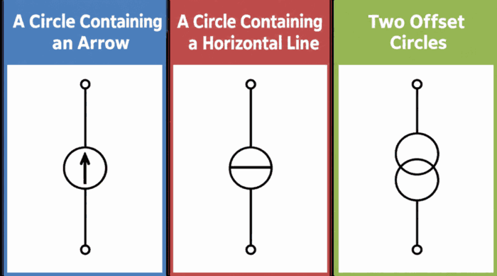
Current sources are represented by symbols such as those shown above. The “circle containing an arrow” shown on the far left is commonly used. Each symbol is explained below.
- A circle containing an arrow
- For DC, the arrow indicates the direction of positive current flow. For AC, it indicates the positive reference direction for the current. If the current value is negative, the current flows in the direction opposite to the arrow.
- A circle containing a horizontal line
- This is the graphical symbol specified in JIS C 0617 / IEC 60617 for an ideal current source. It is used for both DC and AC. Parameters such as the current value and its reference direction are indicated near the symbol as needed.
- Two offset circles
- This symbol is sometimes used to represent a current source. The current value and its reference direction are indicated near the symbol as needed.
Voltage Across a Current Source
The following diagram shows how the voltage \(V_R\) across a current source changes when the load resistance \(R\) is varied.

For an ideal current source, the current \(I_R\) through the load resistance \(R\) remains constant, regardless of the value of \(R\).
For example, if a load resistance \(R\) of \(5{\mathrm{[\Omega]}}\) is connected to an ideal current source that supplies \(10{\mathrm{[A]}}\), the voltage \(V_R\) across the load resistance \(R\) (and across the current source) is given by Ohm’s law as follows.
\begin{eqnarray}
V_R=R\times I_R=5\times10=50{\mathrm{[V]}}\tag{4}
\end{eqnarray}
If the load resistance \(R\) doubles to \(10{\mathrm{[\Omega]}}\), the current remains at \(10{\mathrm{[A]}}\), so the voltage \(V_R\) across the current source also doubles.
\begin{eqnarray}
V_R=R\times I_R=10\times10=100{\mathrm{[V]}}\tag{5}
\end{eqnarray}
Thus, for an ideal current source, the voltage \(V_R\) across the current source increases as the load resistance \(R\) increases.
Voltage Across a Current Source When the Load Resistance \(R\) Is Open-Circuited

What happens if the load resistance \(R\) connected to an ideal current source supplying \(10{\mathrm{[A]}}\) is open-circuited? The following diagram illustrates the concept of increasing the load resistance without limit.
Open-circuiting the load resistance \(R\) is ideally equivalent to making its resistance infinite (\(\infty{\mathrm{[\Omega]}}\)).
In this case, as the load resistance \(R\) increases without limit while the current is kept constant, the required terminal voltage \(V_R\) of the current source increases without bound, as shown below.
\begin{eqnarray}
V_R=R×I_R=∞×10=∞{\mathrm{[V]}}\tag{6}
\end{eqnarray}
Because the internal resistance of an ideal current source is also assumed to be infinite, this means that, in the ideal circuit, there is no upper limit to the voltage required to maintain the current. A practical power source, however, has a maximum output voltage, and some power sources also provide overvoltage protection. Its actual terminal voltage therefore does not become infinite. Once the output voltage limit is reached, the source can no longer maintain the set current.
Open-circuiting a practical current source causes its terminal voltage to rise. Depending on the power source and connected equipment, this may lead to electric shock or equipment failure. Check the power source specifications to determine whether an open load is permitted, and do not disconnect the load carelessly while the source is energized.
Current Source vs. Voltage Source
A “current source” is often compared with a “voltage source.”
A current source supplies current to a load, whereas a voltage source supplies voltage to a load.
An ideal current source is modeled as maintaining a constant output current even when the load changes. In contrast, an ideal voltage source is modeled as maintaining a constant output voltage even when the load changes.
Related Article
“voltage source” characteristics, symbols, and internal resistance are explained in detail in the following article. If you are interested, follow the link below to learn more. 続きを見る
What Is a Voltage Source? Characteristics, Symbols, and Internal Resistance
Summary
This article covered the following key points about current sources:
- An ideal DC current source supplies a constant current regardless of the load.
- The internal resistance \(r\) of an ideal current source is infinite. A practical current source can be represented by an ideal current source connected in parallel with an internal resistance.
- When the internal resistance \(r\) is taken into account, the load current is \(I_R=\frac{r}{r+R}I\).
- For an ideal current source, the terminal voltage rises as the load resistance \(R\) increases. For a practical power source, the maximum output voltage must be taken into account.
- An ideal current source maintains a constant output current, whereas an ideal voltage source maintains a constant output voltage.
Thank you for reading.