When studying electric circuits, you may come across the term voltage source.
A voltage source supplies voltage to a circuit. However, ideal and real voltage sources behave differently when a load is connected.
For example, an ideal voltage source maintains a constant output voltage even when the load resistance \(R\) changes. A real voltage source has internal resistance, so its output voltage decreases as the load current increases.
This article uses diagrams to explain the following topics:
- What a voltage source is
- Voltage across the load when the source’s internal resistance \(r\) is zero
- Voltage across the load when the source’s internal resistance \(r\) is taken into account
- Voltage source symbols
- Current flowing through a voltage source
We hope these explanations help you understand voltage sources.
What Is a Voltage Source?
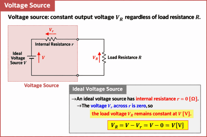
A voltage source is a power source whose output voltage \(V_R\) remains constant regardless of the load resistance \(R\). In particular, an ideal power source that maintains a constant terminal voltage regardless of the load is called an ideal voltage source.
A real voltage source can be represented by a basic equivalent circuit consisting of an ideal voltage source \(V\), which provides a constant voltage, connected in series with an internal resistance \(r\).
An ideal voltage source has an internal resistance \(r\) of \(0{\mathrm{[\Omega]}}\). In this case, the voltage \(V_r\) across the internal resistance is \(0{\mathrm{[V]}}\), so the voltage \(V_R\) across the load resistance \(R\) is given by:
\begin{eqnarray}
V&=&V_r+V_R\\
\\
{\Leftrightarrow}V_R&=&V-V_r\\
\\
&=&V-0\\
\\
&=&V{\mathrm{[V]}}\tag{1}
\end{eqnarray}
Equation (1) does not contain the load resistance \(R\). Therefore, for an ideal voltage source, the voltage \(V_R\) across the load resistance \(R\) remains constant at \(V{\mathrm{[V]}}\), regardless of the value of \(R\).
Key Points
- An ideal voltage source has an internal resistance \(r\) of \(0{\mathrm{[\Omega]}}\).
- In this case, the voltage \(V_R\) across the load resistance \(R\) remains constant regardless of the value of \(R\).
Next, let’s consider how the voltage \(V_R\) across the load res
Voltage Across the Load When Internal Resistance \(r\) Is Taken into Account

For a real voltage source, the internal resistance \(r\) cannot always be treated as \(0{\mathrm{[\Omega]}}\). In this case, the voltage of the ideal voltage source \(V\), which provides a constant voltage, is divided between the internal resistance \(r\) and the load resistance \(R\). The voltage \(V_R\) across the load resistance \(R\) is therefore given by:
\begin{eqnarray}
V_R=\frac{R}{r+R}V{\mathrm{[V]}}\tag{2}
\end{eqnarray}
Here, \(V\) is the ideal source voltage \({\mathrm{[V]}}\), \(r\) is the source’s internal resistance \({\mathrm{[\Omega]}}\), \(R\) is the load resistance \({\mathrm{[\Omega]}}\), and \(V_R\) is the voltage across the load resistance \({\mathrm{[V]}}\).
Equation (2) contains the load resistance \(R\). Therefore, when the value of \(R\) changes, the voltage \(V_R\) across the load resistance also changes. As \(R\) decreases, the current increases, causing a larger voltage drop across the internal resistance \(r\).
For an ideal voltage source, the internal resistance \(r\) is \(0{\mathrm{[\Omega]}}\), so the voltage \(V_R\) across the load resistance \(R\) becomes:
\begin{eqnarray}
V_R&=&\frac{R}{r+R}V\\
\\
&=&\frac{R}{0+R}V\\
\\
&=&V{\mathrm{[V]}}\tag{3}
\end{eqnarray}
When the internal resistance \(r\) is \(0{\mathrm{[\Omega]}}\), the load resistance \(R\) cancels out of the equation. This shows that, for an ideal voltage source, the voltage \(V_R\) across the load resistance \(R\) remains constant at \(V{\mathrm{[V]}}\), regardless of the value of \(R\).
Voltage Source Symbols
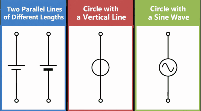
Voltage sources are represented by symbols such as those shown above. Two parallel lines of different lengths are commonly used for a DC source, while a circle containing a sine wave is commonly used for an AC voltage source. Each symbol is explained below.
- Two parallel lines of different lengths
- The longer line represents the positive (+) terminal, and the shorter line represents the negative (−) terminal.
- The shorter line is sometimes drawn slightly thicker. However, this is not necessary as long as the difference in length clearly indicates the polarity.
- A circle containing a vertical line
- This is the graphical symbol specified in JIS C 0617 / IEC 60617 for an ideal voltage source. Parameters such as polarity and voltage are indicated near the symbol as needed.
- A circle containing a sine wave
- This is a common symbol used to represent a sinusoidal AC voltage source.
Current Flowing Through a Voltage Source
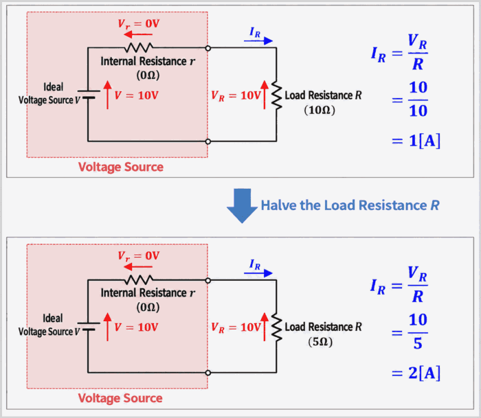
or an ideal voltage source, the voltage \(V_R\) across the load resistance \(R\) remains constant regardless of the value of \(R\).
For example, suppose a load resistance \(R\) of \(10{\mathrm{[\Omega]}}\) is connected to an ideal voltage source that provides \(10{\mathrm{[V]}}\). According to Ohm’s law, the current \(I_R\) through the load resistance is:
\begin{eqnarray}
I_R=\frac{V}{R}=\frac{10}{10}=1{\mathrm{[A]}}\tag{4}
\end{eqnarray}
If the load resistance \(R\) is halved to \(5{\mathrm{[\Omega]}}\), the voltage remains at \(10{\mathrm{[V]}}\), so the current \(I_R\) doubles:
\begin{eqnarray}
I_R=\frac{V}{R}=\frac{10}{5}=2{\mathrm{[A]}}\tag{5}
\end{eqnarray}
Thus, for an ideal voltage source, the current \(I_R\) flowing through the source increases as the load resistance \(R\) decreases.
Voltage Across the Voltage Source When the Load Resistance \(R\) Is Short-Circuited
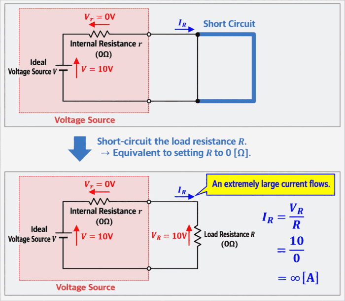
What happens if the load resistance \(R\) connected to an ideal voltage source providing \(10{\mathrm{[V]}}\) is short-circuited?
Short-circuiting the load resistance \(R\) is ideally equivalent to reducing \(R\) to \(0{\mathrm{[\Omega]}}\).
In this case, the calculated current \(I_R\) through the voltage source is expressed as follows, indicating an extremely large current:
\begin{eqnarray}
I_R=\frac{V}{R}=\frac{10}{0}=∞{\mathrm{[A]}}\tag{6}
\end{eqnarray}
Because an ideal voltage source is also assumed to have an internal resistance of \(0{\mathrm{[\Omega]}}\), this means that the short-circuit current has no upper limit in the ideal circuit model. Real power sources, however, have internal resistance, wiring resistance, and other resistances. Depending on the source, overcurrent protection or current limiting may also operate. Therefore, the actual short-circuit current is not infinite.
Short-circuiting a real power source can cause a very large current to flow, potentially resulting in overheating, damage, or fire. Do not intentionally short-circuit a power source’s output terminals.
Summary
This article explained the following topics about voltage sources:
- What a voltage source is
- Voltage across the load when the source’s internal resistance \(r\) is zero
- Voltage across the load when the source’s internal resistance \(r\) is taken into account
- Voltage source symbols
- Current flowing through a voltage source
Thank you for reading.