When reading circuit diagrams, you will often see the symbol for ground (GND).
Do you know what ground (GND) means?
You may also encounter the closely related terms earth ground and earthing.
- What is the difference between circuit ground (GND) and earth ground?
- What types of ground (GND) and earthing are there?
- How do the circuit symbols for ground (GND) and earthing differ?
This article uses diagrams to explain ground (GND) and earthing: their meanings, types, differences, and circuit symbols in a beginner-friendly way.
Circuit Ground (GND) vs. Earth Ground
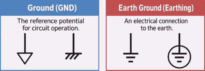
In a circuit, ground (GND) refers to the reference potential for circuit operation.
An earth ground is an electrical connection to the earth.
In simple terms, circuit ground (GND) identifies the reference used within a circuit, while an earth ground provides a connection to the earth. A connection labeled GND is not necessarily connected to the earth.
Note
Terminology varies by region and context. In electrical installations, earthing and grounding often refer to the same connection to earth: “earthing” is the usual British/IEC term, while “grounding” is the US term. In electronics, ground (GND) can also mean the circuit’s reference potential, even without an earth connection. This article distinguishes that circuit ground from an earth ground; it does not treat earthing and grounding as universally different functions.
Types of Ground and Earth Connections
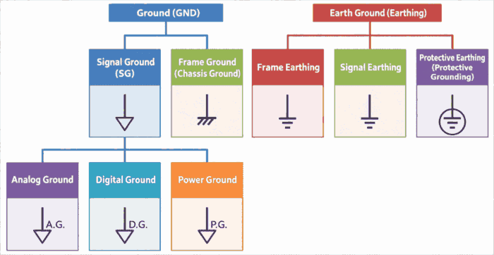
Ground (GND) and earthing can be classified by their purpose and connection point, as shown above. Each type is explained in more detail below.
As the diagram shows, ground (GND) includes signal ground (SG) and frame ground (FG), while earthing includes frame earthing, signal earthing, and protective earthing.
When a system contains analog circuits, digital circuits, and power circuits, labels such as A.G., D.G, and P.G may be used to identify the signal ground (SG) associated with each type of circuit.
For example, A.G. indicates analog ground (the signal ground of an analog circuit).
The diagram below shows an example of how ground (GND) and earthing are used.
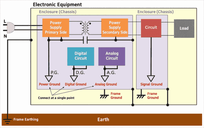
The following sections explain each type.
Ground (GND)
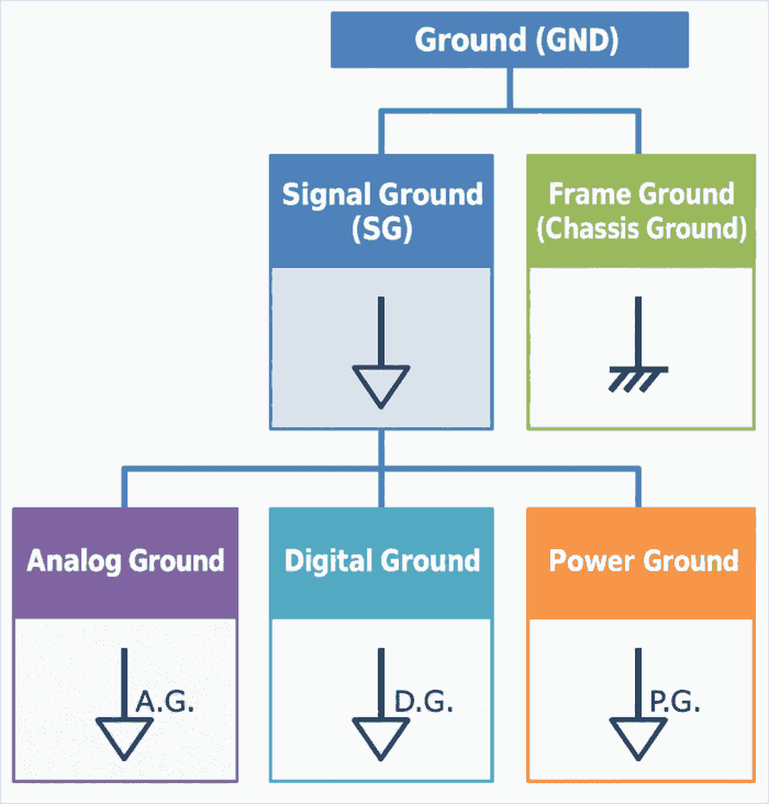
Ground (GND) refers to the reference potential for circuit operation.
Ground (GND) is not necessarily connected to the earth.
An unstable reference potential can cause a circuit to malfunction. It is therefore important to keep ground (GND) as stable as possible.
Types of ground (GND) include frame ground (FG), signal ground (SG), analog ground, digital ground, and power ground.
Note
- Ground (GND) represents the reference potential for circuit operation. However, not every circuit diagram includes a ground symbol.
- The earth provides the most stable potential. If a connection to the earth is not possible, connecting to a conductor with a large capacitance is preferable. A larger capacitance reduces changes in potential caused by changes in current.
Related Article
Understanding GND is easier when you distinguish electric potential, the electrical level relative to a reference, from voltage, the potential difference between two points. For more details, see the following article on the difference between electric potential and voltage.
Frame Ground (FG)

When the metal enclosure (chassis) or frame of a product serves as the reference for circuit operation, it is called frame ground (FG).
In a product containing multiple circuits, a common reference potential is needed to coordinate voltages between those circuits.
Depending on the design, the GND connections of individual circuits are connected to the enclosure (chassis), so that they share the chassis as their reference potential.
Note
- Frame ground is also called chassis ground.
- In aircraft, the metal airframe may be used as the reference for electrical potential.
- In vehicles, the vehicle body may be used as the reference for electrical potential.
Signal Ground (SG)
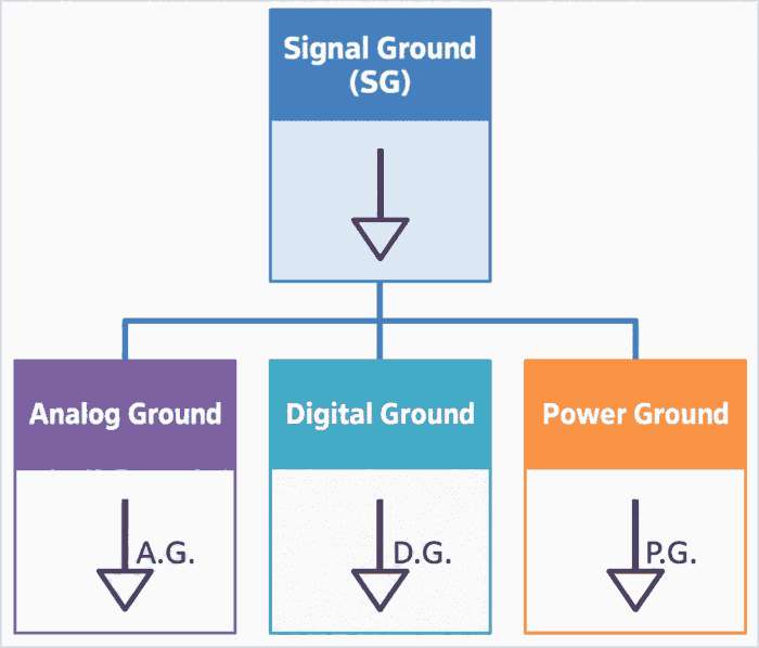
The ground of an individual circuit may be called signal ground (SG) to distinguish it from frame ground (FG).
Thus, signal ground (SG) refers to the reference potential for circuit operation.
In a system containing analog circuits, digital circuits, and power circuits that handle substantial power, routing the signal ground connections separately according to the characteristics of each circuit and joining them at a single point can reduce interference between circuits.
If the grounds are not joined at a single point, currents from digital or power circuits can create potential differences along the GND wiring and affect analog circuits that handle small signals. However, single-point grounding is not the best approach for every circuit. Follow the relevant IC datasheets and other manufacturer guidance when deciding how to connect the grounds.
To distinguish the signal grounds of different circuit types, the signal ground of an analog circuit is called analog ground (AGND), that of a digital circuit is called digital ground (DGND), and that of a power circuit is called power ground (PGND).
Analog Ground (AGND)
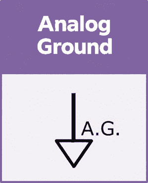
Analog ground (AGND) is the signal ground (the reference potential for circuit operation) of an analog circuit.
Digital Ground (DGND)
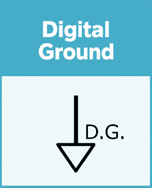
Digital ground (DGND) is the signal ground (the reference potential for circuit operation) of a digital circuit.
Power Ground (PGND)

Power ground (PGND) is the signal ground (the reference potential for circuit operation) of a power circuit that carries large currents.
In power supply circuits, a Y capacitor may be connected between the circuit and frame ground (FG) to reduce noise.
Earth Grounding (Earthing)
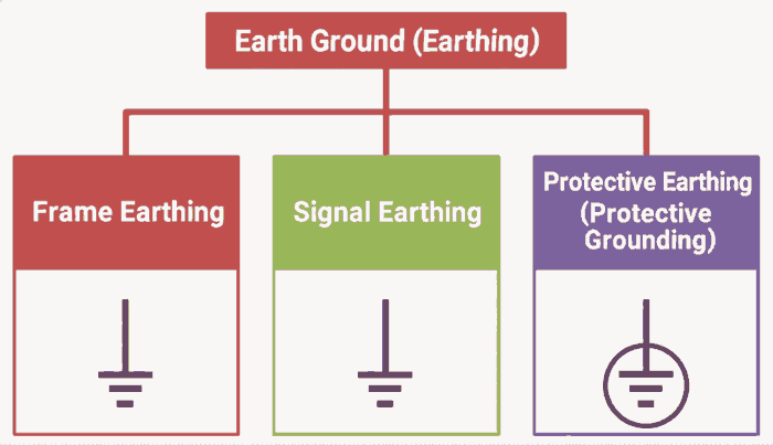
Earthing means making a connection to the earth.
The term earthing describes an electrical connection to the earth.
The earth is the largest electrical conductor on the planet. Earthing can therefore stabilize the reference potential used for circuit operation.
Types of earthing include frame earthing, signal earthing, and protective earthing.
Frame Earthing
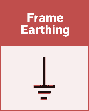
Frame earthing means connecting frame ground to the earth.
If frame ground is not earthed, current may flow through a person who touches the frame of the product.
For this reason, earthing frame ground is desirable for electrical safety. Proper earthing can reduce the risk of electric shock if leakage occurs.
In a line-to-neutral single-phase supply, live (L, also called line or hot) and neutral (N) provide the operating current. Appliances such as microwave ovens and refrigerators may also use a third conductor for protective earthing. Depending on the country and product, it may be incorporated into the power cord and connected through the plug’s grounding contact, or provided as a separate earth lead. Protective conductors may be green or green-and-yellow, depending on local requirements.
This conductor connects the appliance’s enclosure (chassis) to the protective earthing system. The connection may be made through a grounded outlet or a designated earth terminal, depending on the installation. Follow the manufacturer’s instructions and local electrical requirements; any work on earthing electrodes or fixed wiring should be carried out by a qualified electrician.
Signal Earthing
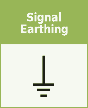
Signal earthing means connecting signal ground—the reference potential for circuit operation—to the earth to make its potential more stable.
This connection is called signal earthing to distinguish it from frame earthing.
Protective Earthing
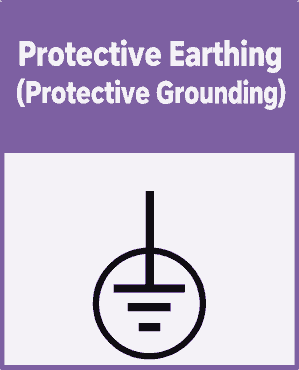
Protective earthing means connecting an equipment enclosure or similar part to the earth for protection against electric shock.
Connecting equipment to the earth can reduce the risk of electric shock if leakage occurs in appliances such as microwave ovens or washing machines. This ground symbol is not commonly encountered in electronic circuit schematics. It is used, for example, to identify protective earth terminals on equipment.
Protective earthing is also called protective grounding in US terminology.
Summary
This article explained ground (GND) and earthing, with the following key takeaway:
- In this article, ground (GND) refers to the reference potential for circuit operation, while earthing refers to making a connection to the earth.
Thank you for reading.